background image

5-2 


Handling Project Data 


The Model 2701-B can store approximately 1000 readings. 

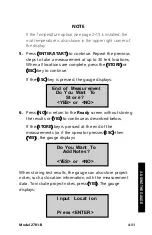
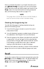
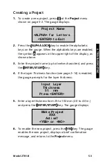
The 

Project 

and 

Store 

functions allow handling of 

measurement data. Measurement results are stored in files 

(memory locations) called 

projects

, which are named by the 

operator. The 

Project 

function allows the operator to create a 

new project, view project data, select a project (make an 

existing project active so that additional data may be added 

to it), output the data stored in the project, or erase projects. 

The 

Store 

function allows the operator to store measurement 

results and other test-identifying information in a selected 

project. Refer to page 5-10 for information on the 

Store 

function. 
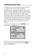
To access the 

Project 

function, press the 

PROJ


key. The 

gauge displays the 

Project 

menu: 


Use the arrow keys to scroll through the menu options. Use 

the numeric keys to select a menu option. Press 

ESC


to 

return to the 

Ready 

screen. 


- Pr oj ect - 

4.  Er ase 
5.  Out put 


- Pr oj ect - 

1.  Sel ect 
2.  Vi  ew 
3.  Cr eat e 

Summary of Contents for 2701-B

Page 1: ...ion Model 2701 B PaveTracker Plus Troxler Electronic Laboratories Inc 3008 Cornwallis Rd P O Box 12057 Research Triangle Park NC 27709 U S A Phone 1 877 TROXLER Outside the U S A 1 919 549 8661 Fax 1...

Page 2: ...al including photocopying recording or information storage and retrieval systems for any purpose without the express written permission of Troxler Electronic Laboratories Inc 409 is a trademark of the...

Page 3: ...ver it appears in this manual or on safety signs affixed to the machine this is to make all aware of the potential for personal injury and to be cautious when these images are present Always observe a...

Page 4: ...Drive Downers Grove IL 60515 Phone 1 630 261 9304 Fax 1 630 261 9341 TroxTechSupport troxlerlabs com Western Office Service Center 11300 Sanders Drive Suite 7 Rancho Cordova CA 95742 Phone 1 916 631 0...

Page 5: ...e technology now offers the PaveTracker Plus an electromagnetic sensing device that quickly gives an indication of the density of asphalt pavement The Model 2701 B Manual of Operation and Instruction...

Page 6: ...ONVENTIONS USED IN THIS MANUAL Throughout this manual the following symbols and special formatting are used to reveal the purpose of the text NOTE Notes indicate important information that must be rea...

Page 7: ...ructions for setting up starting and operating the unit Chapter 3 Adjusting Measurements Provides instructions for using offsets and mix calibration Chapter 4 Using the Gauge Provides instructions for...

Page 8: ...y the operator Standards to which Conformity is Declared EN 55011 1998 A1 1999 A2 2002 Industrial Scientific and Medical ISM Radio Frequency Equipment EN 61326 1997 A1 1998 A2 2001 A3 2002 Electrical...

Page 9: ......

Page 10: ...ection against harmful interference when the equipment is operated in a commercial environment This equipment generates uses and can radiate radio frequency energy and if not used in accordance with t...

Page 11: ...STARTED Keypad 2 2 Turning the PaveTracker Plus On 2 4 Status 2 6 Setup Menu 2 7 Target 2 15 Mode 2 18 CHAPTER 3 ADJUSTING MEASUREMENTS Introduction 3 2 Offset 3 3 Mix Calibration 3 6 CHAPTER 4 USING...

Page 12: ...PPENDIX B MENU MAP Menu Map Description B 2 APPENDIX C SPECIFICATIONS Measurement Specifications C 2 Electrical Specifications C 3 Mechanical Specifications C 4 INDEX WARRANTY LIST OF FIGURES Figure T...

Page 13: ...r 1 1 I In nt tr ro od du uc ct ti io on n This chapter covers the following topics and tasks An introduction to your new PaveTracker Plus Included parts and accessories Inspection and unpacking Assem...

Page 14: ...gregation areas of low density and overall pavement uniformity The PaveTracker Plus is a precision device that is designed to provide many years of trouble free service As any precision device the Pav...

Page 15: ...Model 2701 B 1 3 HANDLE CARRYING HANDLE DISPLAY KEYPAD BATTERY CHARGER INPUT SERIAL PORT POWER SWITCH Figure 1 1 Model 2701 B PaveTracker Plus 1 INTRODUCTION...

Page 16: ...e backlit making them easy to see day or night The gauge includes a replaceable protective adhesive backed bottom cover disc on its bottom surface The protective cover provides thermal protection for...

Page 17: ...sounds a longer tone when the operator presses an invalid key or if the gauge displays an error message The external beeper performs the same functions and can be enabled or disabled as desired by th...

Page 18: ...s a built in reference standard which provides a density measurement standard for taking reference readings 3 The ac charger and dc adapter are used to charge the gauge batteries The ac charger accept...

Page 19: ...ase and or any other part or accessory appears damaged notify the carrier and your Troxler representative immediately 2 Check the shipping case for the following Model 2701 B PaveTracker Plus Carrying...

Page 20: ...1 8 NOTES...

Page 21: ...St ta ar rt te ed d This chapter covers the following topics and tasks Getting started with the PaveTracker Plus Using the keypad Turning the gauge on Setting up the gauge Checking the Status of the g...

Page 22: ...RT Keypad The Model 2701 B keypad Figure 2 1 allows the operator to access the gauge software Troxler designed the keypad for ease of use with large keys and an anti glare coating Note that the functi...

Page 23: ...ing Continuous or Segregation 2 18 OFFSET Enable disable or change a density offset 3 3 REF Take a reference reading 4 2 SPACE Enter a space LIGHT Manually toggle the keypad and LCD backlights on and...

Page 24: ...t the gauge is working properly The gauge first performs a brief self test followed by a test of the display Following the test period the gauge displays the Ready screen The operator can access any g...

Page 25: ...acklights and most of the electronics are turned off but all data and gauge settings are protected To exit sleep mode press any key If no key is pressed for 60 minutes the gauge shuts down automatical...

Page 26: ...the time and date of the last reference reading see page4 2 and GPS satellite and fix status To access this information press the STATUS key The gauge displays To scroll through the displays use the...

Page 27: ...Setup menu press the SETUP key The gauge displays To scroll through the Setup menu use the arrow keys screens that have options the operator can scroll through are indicated with the up down arrow sy...

Page 28: ...change the date and time and to select the display format for each To access the Date Time menu press 2 at the Setup menu shown on page 2 7 The gauge displays the Date Time menu From this screen the o...

Page 29: ...uge sets the time and returns to the Date Time menu Change Date To change the date press 2 at the Date Time menu The gauge displays Note that in this example the time is displayed in mm dd yyyy format...

Page 30: ...time format and returns to the Date Time menu Date Format The gauge can display the date in either mm dd yyyy or dd mm yyyy format where mm month dd day and yyyy year To select the desired date format...

Page 31: ...omer name press 4 at the Setup menu shown on page 2 7 The gauge displays the current customer name on the second line To change the customer name press YES The gauge displays Press the ALPHA LOCK key...

Page 32: ...f confirmation message and returns to the Setup menu GPS Option The PaveTracker Plus can be equipped with an optional GPS receiver which enables the gauge to store each measurement with precise coordi...

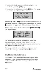
Page 33: ...o enable the alphabetic keys on the gauge When the alphabetic keys are enabled the symbol Aappears in the upper right of the display as shown above Enter the new user ID and press ENTER START The gaug...

Page 34: ...page 5 3 The layer thickness value is then stored along with other measurement data in the active project To enable or disable the Layer Thickness function press 9 from the Setup menu shown on page 2...

Page 35: ...he test material With the Target function the operator can enter a new target value enable a stored target value or disable a target value To access the Target function press the TARGET key The gauge...

Page 36: ...lays To store the value press the YES key To use the value now without storing it for later use press the NO key If YES is pressed the target value the gauge displays The gauge can store the target va...

Page 37: ...Disable a Target Value To disable the current target value press 6 at the target value menu The gauge disables the target value displays a brief confirmation message and returns to the Ready screen 2...

Page 38: ...mode In segregation mode the operator can take up to 30 measurements at selected locations The gauge then displays the high low and average density of the readings This mode enables the operator to de...

Page 39: ...t te er r 3 3 A Ad dj ju us st ti in ng g M Me ea as su ur re em me en nt ts s This chapter covers the following topics and tasks Adjust gauge measurements using offsets Using mix calibration slope an...

Page 40: ...ndard The result of this comparison is used to automatically adjust gauge measurements For increased accuracy measurements can be adjusted using density offset and mix calibration values described in...

Page 41: ...g the PaveTracker Plus inspect the protective cover of the bottom surface of the gauge s sensor Ensure that the cover is in good condition and has no deep scratches or buildup of material If necessary...

Page 42: ...determined by a core analysis is 150 pcf and the density measured by PaveTracker Plus is 146 pcf the density offset is 4 pcf NOTE For best results repeat the above procedure to determine the density...

Page 43: ...the arrow keys to select the offset sign positive or negative The gauge displays Enter the density offset as determined from the procedure on page 3 3 and press ENTER START The gauge enables the new...

Page 44: ...gauge to calculate both a slope and an intercept for the test material measurements must be performed at a minimum of three locations Also the difference between the minimum and maximum reading must...

Page 45: ...x calibration based on gauge measurements and values determined by an alternate method press 1 to access the Data Pairs function To enter slope and intercept values manually press 2 to access the Slop...

Page 46: ...nter those for the next location When the measured and actual densities for each location have been entered press the ENTER START key to calculate the mix calibration The gauge displays To return to t...

Page 47: ...bration displays a brief confirmation message and returns to the Setup menu Slope Intercept The Slope Intercept function is used to manually enter the slope and or intercept for a particular material...

Page 48: ...can store the mix calibration in one of four memory cells Use the numeric keys to store the mix calibration Note that this will replace any mix calibration that was previously stored in that cell The...

Page 49: ...ap pt te er r 4 4 U Us si in ng g t th he e G Ga au ug ge e This chapter covers the following topics and tasks Referencing the gauge Preparing measurement sites Setting measurement mode Taking measur...

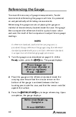
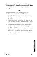
Page 50: ...d Always reference the gauge using the reference standard provided with your unit Each reference standard is unique do not interchange gauges and cases 1 Turn the gauge on as described on page 2 4 At...

Page 51: ...sensor press firmly around the perimeter of the cover Ensure that the cover and reference standard are totally clean and free of any asphalt residue moisture or debris Clean with WD 40 or other suitab...

Page 52: ...ure see page 2 6 allows the operator to view the current gauge status This feature provides a quick overview of the battery voltage sensor temperature selected measurement units the date and time of t...

Page 53: ...lowed to cool before continuing If measurements are performed before the gauge is allowed to cool the warning symbol is displayed NOTE Before using the gauge inspect the protective cover of the bottom...

Page 54: ...elect the mode as described on page 2 18 Place the gauge on the test site and press ENTER START The gauge displays the measurement results updated every second as shown 2 Press ESC to return to the Re...

Page 55: ...ude and longitude will be displayed to the nearest hundredth 1 100 of a second If a GPS location is determined but the WAAS information is unavailable the latitude and longitude will be displayed to t...

Page 56: ...take a measurement in averaging mode select the mode as described on page 2 18 3 Press the ENTER START key The gauge displays 4 Place the gauge on the first test site and press ENTER START The gauge...

Page 57: ...sses ESC then YES the gauge displays When storing test results the gauge can also store project notes such as location information with the measurement data To include project notes press YES The gaug...

Page 58: ...e is a large degree of segregation in the area being measured 1 Extend the telescoping handle see Figure 1 1 to reduce the bending required while taking measurements 2 To take a measurement in segrega...

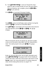
Page 59: ...he gauge displays 6 Press NO to return to the Ready screen without storing the results or YES to continue as described below If the STORE key is pressed at the end of the measurements or if the operat...

Page 60: ...e correct measurement mode 2 Turn off disable all operator installed density offsets and mix calibrations See Chapter 3 for more information 3 Place the gauge on the reference standard and verify that...

Page 61: ...Model 2701 B 5 1 C Ch ha ap pt te er r 5 5 P Pr ro oj je ec ct t D Da at ta a This chapter covers the following topics and tasks Using the Projects function Storing data A TROUBLESHOOTING...

Page 62: ...ive so that additional data may be added to it output the data stored in the project or erase projects The Store function allows the operator to store measurement results and other test identifying in...

Page 63: ...cters and press the ENTER START key 4 If the Layer Thickness function see page 2 14 is enabled the gauge prompts for the layer thickness 5 Enter a layer thickness from 25 to 102 mm 2 0 to 4 0 in and p...

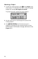
Page 64: ...cts are stored If a project has been created the gauge displays 2 Use the arrow keys to scroll through the names of the existing projects 3 Press ENTER START when the desired project is displayed The...

Page 65: ...s 2 at the Project menu The gauge displays 2 Use the arrow keys to scroll through the project names 3 Press ENTER START when the gauge displays the desired project name If any measurement data has bee...

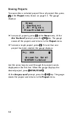
Page 66: ...urns to the Project menu To erase a single project press 1 If more than one project has been created the gauge displays Use the arrow keys to scroll through the project names displayed on the first li...

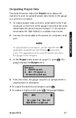
Page 67: ...cable to the printer or computer serial port NOTE To upload data to a computer use the HyperTerminal application available from the Windows Accessories menu This application can be used to transfer da...

Page 68: ...rinter The Spreadsheet option is sent in a comma delimited format which can then be imported easily into a spreadsheet program such as Microsoft Excel The information output using the Spreadsheet opti...

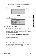
Page 69: ...the correct speed ensuring that all the data is included in the hard copy To print project data press 6 at the Project menu shown on page 5 2 The gauge displays the Output menu shown on page 5 7 NOTE...

Page 70: ...This value is displayed only if the Layer Thickness function is enabled Record number Measurement time Measurement date Measurement mode Gmb Marshall This value is 0 0 if the Gmb Marshall target is 0...

Page 71: ...n taking measurements in continuous mode the operator can store the data in the selected project by pressing the STORE key at any time when the gauge is displaying measurement data or after returning...

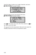
Page 72: ...ENTER START The gauge displays Press 1 if the station was to the left of the centerline or 2 if the station was to the right The gauge stores the measurement data and notes under the selected project...

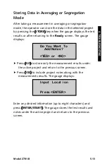
Page 73: ...een The gauge displays Press NO to store only the measurement results under the active project and return to the previous screen Press YES to include project notes along with the measurements results...

Page 74: ......

Page 75: ...le es sh ho oo ot ti in ng g a an nd d S Se er rv vi ic ce e This appendix provides details for troubleshooting and servicing the Model 2701 B PaveTracker Plus For further details contact the nearest...

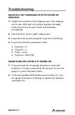
Page 76: ...t cable is being used 3 Ensure that the printer computer baud rate is 9 600 bps 4 Ensure that all other parameters match Data bits 8 Stop bits 2 Parity none Protocol DSR DTR GAUGE TURNS OFF AFTER IT I...

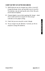
Page 77: ...fe The batteries may be reaching the end of their life cycle and should be replaced 2 Charger adapter may not be supplying full charge check the ac outlet and the dc output 12 V dc using a voltmeter o...

Page 78: ...al temperature of the gauge reaches a level that is considered excessive the beeper will sound and the following warning message is displayed The gauge should be taken to a shaded or air conditioned e...

Page 79: ...fter completing any memory store functions already in progress Troxler recommends that the operator recharge the NiMH batteries The NiMH batteries can be fully recharged in only 2 5 hours Charging To...

Page 80: ...n the screws and set them aside 4 Carefully lift the old NiMH battery pack from the gauge 5 Unplug the battery cable from the battery connection on the top circuit board Gently squeeze the connector t...

Page 81: ...to provide high impact strength and to offer excellent compatibility with many industrial solvents and petro chemicals The top shell may be cleaned with mild low alkaline soap and water Other approved...

Page 82: ...g PN 113103 Cover Replacement Kit which includes three discs To remove the old protective cover disc 1 Turn the gauge over so that its bottom surface is exposed To prevent damage to the keypad or disp...

Page 83: ...3 Align the replacement cover disc with the sensor and press it into place Smooth out the disc to eliminate air bubbles NOTE Do not remove and re install the same cover disc as the adhesive will be w...

Page 84: ...assembly 113103 Bottom cover replacement kit includes three replacement bottom cover discs 110374 NiMH battery assembly Accessories PART DESCRIPTION 104156 DC charger 110403 AC adapter 106514 0002 Ser...

Page 85: ...are having with the instrument Shipment method to Troxler and for return shipment Shipping and billing address not P O Box street address and zip code Telephone number and contact for questions from T...

Page 86: ...Appendix A 12 NOTES...

Page 87: ...Model 2701 B Appendix B 1 A Ap pp pe en nd di ix x B B M Me en nu u M Ma ap p This appendix provides a map of the various menus in the Model 2701 B PaveTracker Plus control software B MENU MAP...

Page 88: ...Vi ew 3 Cr eat e 4 Er ase Er ase 1 One Pr oj ect 2 Al l Pr oj ect s This indicates that by pressing the PROJ key the operator accesses the Pr oj ect menu The first three items under the Pr oj ect men...

Page 89: ...5 Out put Out put 1 One Pr oj ect 2 Al l Pr oj ect s SETUP Set up 1 Set Uni t s Uni t s 1 Engl i sh 2 Metr i c 2 Dat e Ti me Dat e Ti me 1 Change Ti me 2 Change Dat e 3 Ti meFor mat Ti me For mat 1 AM...

Page 90: ...New Ent r y Met hod 1 Dat a Pai r s 2 Sl ope I nt er cept 6 Di sabl e 7 Vi ew 8 Layer Thi ckness Thi ckness Opt i on 1 ON 2 OFF TARGET Tar get 1 Gmb Marshal l Gmb MA Val ue 1 2 Items 1 through 4 repre...

Page 91: ...odel 2701 B Appendix B 5 Figure 5 1 Model 2701 B Menu Map Continued MODE Mode 1 Cont i nuous 2 Aver agi ng 3 Segr egat i on OFFSET Dens i t y Of f set 1 Enabl e 2 Di sabl e 3 Change Off set B MENU MAP...

Page 92: ...Appendix B 6 NOTES...

Page 93: ...2701 B Appendix C 1 A Ap pp pe en nd di ix x C C S Sp pe ec ci if fi ic ca at ti io on ns s This appendix contains gauge and measurement specifications for the Model 2701 B PaveTracker Plus C SPECIFIC...

Page 94: ...vement density in lb ft3 and kg m3 Precision 0 2 lb ft3 3 2 kg m3 at 1 Sigma on reference standard Probe Non nuclear non capacitance measuring field Probing depth Up to 4 45 cm 1 75 in Measurement tim...

Page 95: ...me Before 5 minutes between keypresses Sleep Mode no loss of data or previous status Time Before Automatic 60 minutes of complete inactivity Shutdown Liquid Crystal Display Alphanumeric 4 line 20 char...

Page 96: ...Carrying Case Size 53 34 W 44 45 D 24 13 H cm 21 0 W 17 5 D 9 5 H in Weight Without 4 8 kg 10 5 lb Telescoping Handle Shipping Weight 13 7 kg 30 1 lb Operating Temperature 0 to 70 C Ambient 32 to 158...

Page 97: ...ndix D 1 A Ap pp pe en nd di ix x D D G Gl lo ob ba al l P Po os si it ti io on ni in ng g S Sy ys st te em m This appendix gives an overview of how the optional GPS receiver operates and its accuracy...

Page 98: ...that monitor and control those satellites The satellites orbit the earth at an altitude of approximately 11 000 miles and constantly transmit signal information back to earth A GPS receiver uses this...

Page 99: ...that the signals from the WAAS satellite may not be available to gauge users in locations where trees mountains and other large objects obstruct the view of the horizon On other locations the GPS rece...

Page 100: ...racy Fix Quality GPS reading with WAAS Within 3 m 10 ft Latitude and longitude displayed to nearest 1 100 second GPS reading without WAAS Within 15 m 50 ft Latitude and longitude displayed to nearest...

Page 101: ...harge A 5 Replace A 6 Beeper external 2 12 Bottom cover disc 1 4 Replacing A 8 C Carrying case 1 6 Charge batteries A 5 Charger ac 1 6 Cleaning base and top shell A 7 Continuous mode 4 6 Create projec...

Page 102: ...3 Enable Density offset 3 4 Mix calibration 3 7 Target 2 17 Enter target 2 17 Erase projects 5 6 F Format project output 5 8 G Gauge temperature internal A 4 GPS 2 1 2 7 2 8 2 13 4 7 D 1 D 2 I Inspec...

Page 103: ...0 Enable 3 7 New 3 7 Mode Averaging 4 8 Continuous 4 6 Measurement 2 18 Segregation 4 10 Sleep 2 6 C 3 MODE key 2 18 N NiMH battery pack A 5 O Offset 3 3 Options A 10 Output project data 5 7 P Parts 1...

Page 104: ...ver disc A 8 S Segregation mode 4 10 Select project 5 4 Self test 2 5 Service A 11 Set units 2 9 Setup 2 8 SETUP key 2 8 Shutdown automatic 2 6 C 3 Sleep mode 2 6 C 3 Slope Intercept 3 9 Specification...

Page 105: ...4 Target Disable 2 18 Enable 2 17 Enter 2 17 Values 2 16 TARGET key 2 16 Temperature 2 11 Test site preparation 4 4 Time 2 10 Format 2 11 Troubleshooting A 2 U Units measurement 2 9 Unpacking 1 7 User...

Page 106: ...tten and signed agreement THERE ARE NO WARRANTIES WHICH EXTEND BEYOND THE DESCRIPTION ON THE FACE HEREOF AND THIS WARRANTY IS EXPRESSLY IN LIEU OF ALL OTHER WARRANTIES EXPRESSED OR IMPLIED AND TROXLER...

Reviews: