background image

5–8


STORING DATA 

 
The Model 2701-B can store approximately 1000 readings. As 
described in the previous section, the gauge stores readings under 
the project name that has been enabled. For more information on 
selecting a project, see page 5–2
 
Project data can be output as described on page 5–5. When using the 

Spreadsheet 

option, the gauge outputs the following information for 

each reading: 


Project name 


Layer Thickness 

– This value is displayed only if the 

Layer 

Thickness 

function is enabled.


Record number 


Measurement time 


Measurement date 


Measurement mode 


Gmb (Marshall) 

– This value is 0.0 if the Gmb (Marshall) target 

is 0.0. 


Gmm (Voidless) 

– This value is 0.0 if the Gmm (Voidless) 

target is 0.0. 


Density measurement 


Low density 

– This value is 0.0 if not in 

segregation 

mode. 


High density 

– This value is 0.0 if not in 

segregation 

mode. 


Air voids 

– This value is 0.0 if Gmm (Voidless) target is 0.0. 


Slope 


Offset 


Gmb (Marshall) target 


Gmm (Voidless) target 


Mat temperature

 – This value is 0 if the 

Temperature 

option 

(see page 2–10) is not installed. 


Station ID


User ID 


Location (right or left) of centerline

 – This value is blank if not 

in 

continuous 

mode. 


Distance from centerline

 – This value is 0.0 if not in 

continuous 

mode. 


Summary of Contents for 2701 -B

Page 1: ...tion Model 2701 B PaveTracker Plus Troxler Electronic Laboratories Inc 3008 Cornwallis Rd P O Box 12057 Research Triangle Park NC 27709 U S A Phone 1 877 TROXLER Outside the U S A 1 919 549 8661 Fax 1 919 549 0761 www troxlerlabs com ...

Page 2: ...l including photocopying recording or information storage and retrieval systems for any purpose without the express written permission of Troxler Electronic Laboratories Inc 409 is a trademark of the Clorox Company Excel HyperTerminal Microsoft and Windows are registered trademarks of Microsoft Corporation Fantastic is a trademark of Dow Consumer Products Inc Goo Gone is a registered trademark of ...

Page 3: ...owners Grove IL 60515 Fax 630 261 9341 Western Regional Branch Office 11300 Sanders Drive Suite 7 Rancho Cordova CA 95742 Fax 916 631 0541 Southwestern Branch Office 2016 East Randol Mill Road Suite 406 Arlington TX 76011 Fax 817 275 8562 Florida Service Center 2376 Forsyth Road Orlando FL 32807 Fax 407 681 3188 Troxler European Subsidiary Troxler Electronics GmbH Gilchinger Strasse 33 D 82239 All...

Page 4: ...hnology now offers the PaveTracker Plus an electromagnetic sensing device that quickly gives an indication of the density of asphalt pavement The Model 2701 B Manual of Operation and Instruction contains information on safely using this gauge Also included in this manual are safety warnings gauge setup troubleshooting and general maintenance ...

Page 5: ...rackets and a different typestyle indicate a key or character number or letter to press on the gauge keypad For example Press STORE means to press the key labeled STORE DISPLAY A different typestyle is used in text to indicate information or messages displayed on the gauge DISPLAY Typestyle and shading used to simulate PaveTracker display Diamonds indicate a list of things needed such as equipment...

Page 6: ...by the operator Standards to which Conformity is Declared EN 55011 1998 A1 1999 A2 2002 Industrial Scientific and Medical ISM Radio Frequency Equipment EN 61326 1997 A1 1998 A2 2001 A3 2002 Electrical Equipment for Measurement Control and Laboratory Use Manufacturer Troxler Electronic Laboratories Inc P O Box 12057 3008 Cornwallis Road Research Triangle Park North Carolina 27709 U S A Apparatus Mo...

Page 7: ...le protection against harmful interference when the equipment is operated in a commercial environment This equipment generates uses and can radiate radio frequency energy and if not used in accordance with this instruction manual may cause harmful interference to radio communications Operation of the equipment in a residential area may cause harmful interference It is advised that operation in res...

Page 8: ...viii NOTES ...

Page 9: ...2 GETTING STARTED Keypad 2 2 Turning the PaveTracker Plus On 2 4 Status 2 6 Setup Menu 2 7 Target 2 14 Mode 2 16 CHAPTER 3 ADJUSTING MEASUREMENTS Introduction 3 2 Offset 3 3 Mix Calibration 3 6 CHAPTER 4 USING THE GAUGE Taking a Reference Reading 4 2 Preparing a Test Site 4 4 Taking Measurements 4 5 Recall 4 12 CHAPTER 5 PROJECT DATA Handling Project Data 5 2 Storing Data 5 8 ...

Page 10: ...ng the Base and Top Shell A 6 Replacing the Protective Cover A 7 Replacement Parts A 8 Returning the Gauge for Service A 9 Troxler Service Centers A 10 APPENDIX B MENU MAP Menu Map Description B 2 APPENDIX C MODEL 2701 B SPECIFICATIONS Measurement Specifications C 2 Electrical Specifications C 3 Mechanical Specifications C 4 INDEX WARRANTY ...

Page 11: ...701 B xi LIST OF FIGURES Figure Title Page 1 1 Model 2701 B PaveTracker Plus 1 3 2 1 Model 2701 B Keypad 2 2 B 1 Model 2701 B Menu Map B 3 LIST OF TABLES Table Title Page 2 1 Model 2701 B Keypad Functions 2 3 ...

Page 12: ...xii NOTES ...

Page 13: ...ter provides a brief overview of the Troxler Model 2701 B PaveTracker Plus and includes a list of the gauge parts and accessories and instructions for unpacking and inspecting the gauge CONTENTS Introduction 1 2 Features 1 4 Gauge Parts and Accessories 1 6 Unpacking and Inspection 1 7 ...

Page 14: ...control measurements to check for segregation areas of low density and overall pavement uniformity The PaveTracker Plus is a precision device that is designed to provide many years of trouble free service As any precision device the PaveTracker Plus requires reasonable care and maintenance to ensure its accuracy and reliability The user should Keep the unit clean and free of all road debris Return...

Page 15: ...HANDLE CARRYING HANDLE DISPLAY KEYPAD POWER SWITCH SERIAL PORT BATTERY CHARGER INPUT 1 INTRODUCTION Figure 1 1 Model 2701 B PaveTracker Plus Model 2701 B 1 3 ...

Page 16: ...ernal components and protects the bottom surface of the gauge against wear The carrying case for the Model 2701 B includes a built in reference standard which provides a density measurement standard for taking reference readings The PaveTracker Plus s advanced software provides three test modes continuous averaging and segregation for greater flexibility and multiple applications The software also...

Page 17: ... error message The external beeper performs the same functions and can be enabled or disabled as desired by the operator A serial communications port is mounted on the front of the gauge The serial port is used to output data to a serial device such as a computer or printer The gauge features two handles The right angle handle is used to move and position the gauge while taking measurements A seco...

Page 18: ...rovides a density measurement standard for taking reference readings 3 The ac charger and dc adapter are used to charge the gauge batteries The ac charger accepts 100 240 V ac 47 63 Hz and supplies 12 V dc at 1 8 A The dc adapter allows recharging from a 12 V dc system such as a vehicle cigarette lighter 4 The manual not shown details how to operate and maintain the gauge 5 A printer optional not ...

Page 19: ... If the shipping case and or any other part or accessory appears damaged notify the carrier and your Troxler representative immediately 2 Check the shipping case for the following Model 2701 B PaveTracker Plus Carrying Case PN 113034 Handle PN 113210 AC Charger PN 110403 DC Adapter PN 104156 2701 B Cover Kit PN 113107 containing replacement bottom covers and cleaning wipes Manual of Operation and ...

Page 20: ...1 8 NOTES ...

Page 21: ...ructions for turning the gauge on and setting up the gauge CONTENTS Keypad 2 2 Turning the PaveTracker Plus On 2 4 Status 2 6 Setup Menu 2 7 Set Units 2 8 Date Time 2 8 Temperature Optional 2 10 Customer Name 2 11 External Beeper 2 12 User ID 2 12 Mix Calibration 2 13 Layer Thickness 2 13 Target 2 14 Enable a Target Value 2 14 Enter a New Target Value 2 15 Disable the Target Value 2 15 Mode 2 16 ...

Page 22: ...coating Note that the function keys are available only when the Ready screen is displayed Table 2 1 describes the function of each key 0 1 4 7 2 5 8 3 6 9 ENTER ALPHA LOCK REF MODE TARGET OFFSET ESC RECALL STORE PROJ STATUS YES NO LIGHT BACK SPACE SPACE START SETUP R TM Ready Offset Y 04 08 2004 04 08 PM Prj MY PROJECT Mode Continuous Figure 2 1 Model 2701 B Keypad 2 2 ...

Page 23: ...urement mode Averaging Continuous or Segregation 2 16 OFFSET Enable disable or change a density offset 3 3 REF Take a reference reading 4 2 SPACE Enter a space LIGHT Manually toggle the keypad and LCD backlights on and off 2 5 YES Respond yes to yes no questions NO Respond no to yes no questions ESC Return the display to the Ready screen without storing or updating the data 0 9 Enter numbers and a...

Page 24: ...he software performs two tests to ensure that the gauge is working properly The gauge first performs a brief self test followed by a test of the display Following the test period the gauge displays the Ready screen Ready Offset YES mm dd yyyy hh mm AM Prj PROJECT NAME Mode Continuous The operator can access any gauge function from the Ready screen On the first line the Ready screen displays whethe...

Page 25: ...ta and gauge settings are protected To exit sleep mode press any key If no key is pressed for 60 minutes the gauge shuts down automatically NOTE If the gauge goes into sleep mode while in the continuous measurement mode see page 2 16 the display returns to the Ready screen In averaging or segregation mode the gauge maintains its current state when it enters sleep mode The gauge software monitors t...

Page 26: ...d measurement units see page 2 8 and the time and date of the last reference reading see page 4 2 To access this information press the STATUS key The gauge displays Status Batt Volts Internal Temp F Units English Last Ref hh mma mm dd yy To scroll through the displays use the up and down arrow keys Return to the Ready screen by pressing the ESC key ...

Page 27: ...ickness function To access the Setup menu press the SETUP key The gauge displays Setup 1 Set Units 2 Date Time 3 Temperature Setup 4 Customer Name 5 External Beeper 6 User ID Setup 7 Mix Calibration 8 Layer Thickness To scroll through the Setup menu use the arrow keys screens that have options the operator can scroll through are indicated with the up down arrow symbol in the upper right corner of ...

Page 28: ...ATE TIME The Date Time function allows the operator to change the date and time and to select the display format for each To access the Date Time menu press 2 at the Setup menu shown on page 2 7 The gauge displays the Date Time menu Date Time 1 Change Time 2 Change Date 3 Time Format Date Time 4 Date Format From this screen the operator may change the time date or time date display format Use the ...

Page 29: ...ew time and the arrow keys to toggle between AM and PM Press ENTER START The gauge sets the time and returns to the Date Time menu Change Date To change the date press 2 at the Date Time menu The gauge displays 04 08 2004 mm dd yyyy Input Date and Press ENTER Note that in this example the time is displayed in mm dd yyyy format To change the date format refer to the Date Format section on page 2 10...

Page 30: ...d yyyy or dd mm yyyy format where mm month dd day and yyyy year To select the desired date format press 4 at the Date Time menu The gauge displays Date Format 1 mm dd yyyy 2 dd mm yyyy Use the numeric keys to select the desired format The gauge sets the date format and returns to the Date Time menu TEMPERATURE OPTIONAL An infrared sensor that measures the temperature of the mat is available as an ...

Page 31: ...line Customer Name is CUSTOMER Change Name YES or NO To change the customer name press YES The gauge displays Customer Name A Input Name and Press ENTER Press the ALPHA LOCK key to enable the alphabetic keys on the gauge When the alphabetic keys are enabled the symbol A appears in the upper right of the display as shown above Enter the new name and press the ENTER START key The gauge stores the ne...

Page 32: ...rmation message and returns to the Setup menu USER ID The PaveTracker Plus stores a three character user ID with each measurement To enter or change the user ID press 6 on the Setup menu shown on page 2 7 The gauge displays User ID XXX Do You Want To Change User ID To change the user ID press YES The gauge displays Input User ID A ALPHA for Letters Press ENTER Press the ALPHA LOCK key to enable th...

Page 33: ...ator to enter a thickness value when creating a new project as described on page 5 4 The layer thickness value is then stored along with other measurement data in the active project To enable or disable the Layer Thickness function press 8 on the Setup menu shown on page 2 7 The gauge displays Thickness Option 1 ON 2 OFF Press to Select Press 1 to enable the Layer Thickness function or 2 to disabl...

Page 34: ...or disable a target value To access the Target function press the TARGET key The gauge displays the Target menu Target 1 Gmb Marshall 2 Gmm Voidless Press to Select To enter enable or disable a Gmb Marshall or Gmm Voidless density value press the corresponding numeric key For example to edit the Gmb Marshall value press 1 The gauge displays the Gmb MA Value menu shown below The Gmm Void Value menu...

Page 35: ...NO key If the operator presses the YES key to store the target value the gauge displays Select Memory Cell 1 2 3 4 Press To Select The gauge can store the target value in one of four memory cells Use the numeric keys to store the target value Note that this will replace any target value that was previously stored in the memory cell The gauge enables the target value displays a brief confirmation m...

Page 36: ... this mode In segregation mode the operator can take up to 30 measurements at selected locations The gauge then displays the high low and average density of the readings This mode enables the operator to determine the degree of segregation in the area being measured The Store function see page 5 10 records the most recent results screen when in this mode Before taking a measurement select the appr...

Page 37: ...e measurements using density offsets and mix calibration slope and intercept values for a particular material CONTENTS Introduction 3 2 Offset 3 3 Determining the Density Offset 3 3 Managing Density Offsets 3 4 Mix Calibration 3 6 Enable a Mix Calibration 3 6 New Mix Calibration 3 7 Disable the Mix Calibration 3 10 ...

Page 38: ...the reference standard The result of this comparison is used to automatically adjust gauge measurements For increased accuracy measurements can be adjusted using density offset and mix calibration values described in the following sections To determine the density offset take a gauge reading and compare the measured value to an alternative density value as measured by another method such as using ...

Page 39: ...r Ensure that the cover is in good condition and has no deep scratches or buildup of material If necessary replace the cover as described on page A 7 2 Measure the in place density of the material using the PaveTracker Plus to find the measured density Mark the test site so that nuclear gauge readings or core extraction can be conducted in the same location If the core has already been removed tak...

Page 40: ...ure to determine the density offset at each of several in place locations Then calculate the average density offset MANAGING DENSITY OFFSETS Density offsets are managed using the Density Offset menu To access this menu press OFFSET The gauge displays Density Offset pcf 1 Enable 2 Disable 3 Change Offset The gauge displays the current density offset on the second line To enable the offset press 1 T...

Page 41: ...rrow keys to select the offset sign positive or negative The gauge displays Density Offset pcf Input and Press ENTER Enter the density offset as determined from the procedure on page 3 3 and press ENTER START The gauge enables the new offset and returns to the Ready screen ...

Page 42: ...nts must be performed at a minimum of three locations Also the difference between the minimum and maximum reading must be at least 3 pcf For best results Troxler recommends taking measurements at seven to ten locations To access the Mix Calibration function press 7 on the Setup menu shown on page 2 7 The gauge displays 1 2 3 4 5 New 6 Disable 7 View Selections 1 through 4 show the mix calibrations...

Page 43: ...ally press 2 to access the Slope Intercept function These functions are described in the following sections Data Pairs To determine a new mix calibration based on gauge measurements and values determined by an alternate method press 1 at the Entry Method menu shown above The gauge displays Input Reading 1 0 0 pcf Press ENTER Using the numeric and decimal keys enter the measured density the density...

Page 44: ...ix To return to the Setup menu without saving the mix calibration press the NO key To save the mix calibration press the YES key The gauge requests a mix calibration ID as shown Mix Calib ID ALPHA for Letters Press ENTER Press the ALPHA LOCK key to enable the alphabetic keys on the gauge When the alphabetic keys are enabled the symbol A appears in the upper right of the display as shown above Ente...

Page 45: ...on described on page 3 7 or can be calculated manually To access the Slope Intercept function press 2 on the Entry Method menu shown on page 3 7 The gauge prompts for the slope and intercept values Press ENTER START after each value is entered After both values have been entered the gauge displays Slope Intercept Do you want to accept this mix To return to the Setup menu without saving the mix cal...

Page 46: ...ys to store the mix calibration Note that this will replace any mix calibration that was previously stored in that cell The gauge enables the mix calibration displays a brief confirmation message and returns to the Setup menu DISABLE THE MIX CALIBRATION To disable the current mix calibration press 6 at the mix calibration menu The gauge disables the mix calibration displays a brief confirmation me...

Page 47: ...2701 B PaveTracker Plus Basic use includes taking a reference reading preparing measurement sites setting the measurement mode and taking measurements CONTENTS Taking a Reference Reading 4 2 Preparing a Test Site 4 4 Taking Measurements 4 5 Continuous Mode 4 6 Averaging Mode 4 7 Segregation Mode 4 9 Recall 4 12 ...

Page 48: ...ference standard in the carrying case provided with the specific unit Turn the gauge on as described on page 2 4 At the Ready screen press the REF key The gauge displays Place Gauge on Reference Standard Carrying Case Press START Place the gauge on the reference standard in the carrying case Ensure that the circular sensor on the bottom of the gauge is centered between the four locating pins insid...

Page 49: ...se Repeat the reference reading If the reference reading still does not pass contact Troxler technical support see page A 10 To verify that the gauge is still accurate during use perform the following check Ensure that the gauge is turned on and in measurement mode Turn off disable all operator installed density offsets and mix calibrations See Chapter 3 for specifics Place the gauge on the refere...

Page 50: ...e measurements Locate a smooth site on the asphalt To ensure accurate readings the gauge sensor must be completely in contact with the test material If the gauge rocks then find a more suitable test site If taking a measurement around a core the gauge may be moved a few inches away from the core to level it ...

Page 51: ...t the appropriate measurement mode CAUTION High internal temperatures may damage the gauge s electronic components To reduce the risk of damage DO NOT allow the gauge to sit on hot asphalt for extended periods If the internal temperature of the gauge reaches a level that is considered excessive the beeper will sound and the warning message Internal temp high Allow gauge to cool will be displayed T...

Page 52: ...ments Extend the telescoping handle see Figure 1 1 to reduce the bending required while taking measurements To take a measurement in continuous mode select the mode as described on page 2 16 Place the gauge on the test site and press ENTER START The gauge displays the measurement results updated every second as shown Gmb MA Gmm Voidless D Voids ESC NOTE If the Temperature option see page 2 10 is i...

Page 53: ...ER START key AVERAGING MODE In averaging mode the operator can take up to 30 measurements at selected locations The gauge then calculates the average of the measurements This mode enables the operator to determine the average density over a larger area Extend the telescoping handle see Figure 1 1 to reduce the bending required while taking measurements To take a measurement in averaging mode selec...

Page 54: ...re option see page 2 10 is installed the mat temperature is also shown in the upper right corner of the display Press ENTER START to continue Repeat the steps above to take a measurement at up to 30 test locations When all locations are complete press the STORE or ESC key to continue If the ESC key is pressed the gauge displays End of Measurement Do You Want To Store YES or NO Press NO to return t...

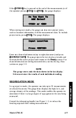
Page 55: ...last displayed results and notes under the active project and returns to the Ready screen For more information on storing measured data see the Storing Data section on page 5 8 NOTE The gauge stores only the data shown in the last display It does not store the results of each individual reading SEGREGATION MODE In segregation mode the operator can take up to 30 measurements at selected locations T...

Page 56: ...w D Den ENTER NOTE If the Temperature option see page 2 10 is installed the mat temperature is also shown in the upper right corner of the display Press ENTER START to continue Repeat the previous steps to take a measurement at up to 30 test locations When all locations are complete press the STORE or ESC key to continue If the ESC key is pressed the gauge displays End of Measurement Do You Want T...

Page 57: ...e measurement data To include project notes press YES The gauge displays Input Location Press ENTER Enter any desired information up to eight characters and press ENTER START The gauge stores the last displayed results and notes under the active project and returns to the Ready screen For more information on storing measured data see the Storing Data section on page 5 8 NOTE The gauge stores only ...

Page 58: ... To view the results of the most recent measurement press the RECALL key from the Ready screen The gauge displays the results of the most recent measurement To return to the Ready screen press the ENTER START key ...

Page 59: ... into the gauge memory Subsequent measurements can then be stored under these project names This chapter describes how to handle project data CONTENTS Handling Project Data 5 2 Select 5 2 View 5 3 Create a Project 5 4 Erase Projects 5 5 Output Project Data 5 5 Storing Data 5 8 Continuous Mode 5 9 Averaging or Segregation Mode 5 10 ...

Page 60: ... project or erase projects The Store function allows the operator to store measurement results and other test identifying information in a selected project Refer to page 5 8 for information on the Store function To access the Project function press the PROJ key The gauge displays the Project menu Project 1 Select 2 View 3 Create Project 4 Erase 5 Output Use the arrow keys to scroll through the men...

Page 61: ... on page 4 12 or any measurement results including project notes stored in a project file using the View function available from the Project menu To view data stored in a project file press 2 at the Project menu The gauge displays Prj XXX mm dd yy hh mmp Rec UID XXX ENTER to select Use the arrow keys to scroll through the project names Press ENTER START when the gauge displays the desired project ...

Page 62: ...as shown above Enter the project name up to twelve characters and press the ENTER START key If the Layer Thickness function see page 2 13 is enabled the gauge prompts for the layer thickness Input Layer Thickness 51 mm Press ENTER Enter a layer thickness from 25 to 102 mm 2 0 to 4 0 in and press the ENTER START key The gauge displays Make Project XXX Active YES or NO To enable the new project pres...

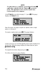
Page 63: ...he Are you sure prompt press the YES key The gauge erases the project and returns to the Project menu To erase all projects press 2 at the Erase menu At the Are You Sure prompt press the YES key The gauge erases all the projects and returns to the Project menu OUTPUT PROJECT DATA The Output function within the Project menu allows the operator to print or upload project data stored in the gauge to ...

Page 64: ...2 All Projects Press to Select From this menu the gauge can print or upload either a single project or all projects To output a single project press 1 The gauge displays Prj XXX Arrows for Scroll ENTER to Select Use the arrow keys to scroll through the project names displayed on the first line When the gauge displays the desired project press ENTER START To output the data from all projects press ...

Page 65: ...rinter The Spreadsheet option is sent in a comma delimited format which can then be imported easily into a spreadsheet program such as Microsoft Excel The information output using the Spreadsheet option is shown on page 5 8 The gauge prints or uploads the project and returns to the Project menu shown on page 5 2 Press the ESC key to return to the Ready screen ...

Page 66: ...number Measurement time Measurement date Measurement mode Gmb Marshall This value is 0 0 if the Gmb Marshall target is 0 0 Gmm Voidless This value is 0 0 if the Gmm Voidless target is 0 0 Density measurement Low density This value is 0 0 if not in segregation mode High density This value is 0 0 if not in segregation mode Air voids This value is 0 0 if Gmm Voidless target is 0 0 Slope Offset Gmb Ma...

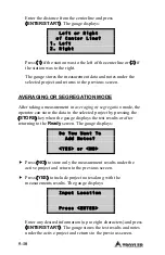
Page 67: ... displaying measurement data or after returning to the Ready screen The gauge displays Do You Want To Add Notes YES or NO f Press NO to store only the measurement results under the active project and return to the previous screen f Press YES to store the station number distance from centerline and location with respect to centerline project notes along with the measurement The gauge displays Input...

Page 68: ...e the operator can store the data in the selected project by pressing the STORE key when the gauge displays the test results or after returning to the Ready screen The gauge displays Do You Want To Add Notes YES or NO f Press NO to store only the measurement results under the active project and return to the previous screen f Press YES to include project notes along with the measurements results T...

Page 69: ...us For further details call the nearest Troxler Service Center or representative CONTENTS Troubleshooting A 2 Internal Gauge Temperature A 3 Batteries A 4 Charging A 4 Replacing the Batteries A 5 Cleaning the Base and Top Shell A 6 Replacing the Protective Cover A 7 Replacement Parts A 8 Accessories A 8 Options A 8 Returning the Gauge for Service A 9 Troxler Service Centers A 10 ...

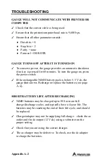
Page 70: ... the power switch If the rechargeable NiMH battery pack is below 5 5 V dc the gauge shuts down Recharge or replace the batteries see page A 4 SHORT BATTERY LIFE AFTER RECHARGING NiMH batteries may be charged up to 500 or more full charge discharge cycles and typically have a 4 year life The batteries may be reaching the end of their life cycle and should be replaced Charger adapter may not be supp...

Page 71: ...d periods If the internal temperature of the gauge reaches a level that is considered excessive the beeper will sound and the following warning message is displayed Internal temp high Allow gauge to cool Press Enter to resume The gauge should be taken to a shaded or air conditioned environment and allowed to cool before continuing If measurements are performed before the gauge is allowed to cool t...

Page 72: ...y after completing any memory store functions already in progress Troxler recommends that the operator recharge the NiMH batteries The NiMH batteries can be fully recharged in only 2 5 hours CHARGING To charge the NiMH batteries plug the charger into the round jack on the front of the gauge Plug the other end of the ac charger into a standard 100 240 V ac outlet The dc adapter may be connected to ...

Page 73: ...e of the unit Clean the screws and set them aside Carefully lift the old NiMH battery pack from the gauge Unplug the battery cable from the battery connection on the top circuit board Gently squeeze the connector to disconnect Plug the battery cable for the new NiMH battery pack into the battery connection on the top circuit board Slide the battery pack into the gauge Replace the battery cover and...

Page 74: ...mild soap such as 409 or Fantastic followed by clean water The Model 2701 B gauge top shell is manufactured from an engineering thermoplastic designed specifically to provide high impact strength and to offer excellent compatibility with many industrial solvents and petro chemicals The top shell may be cleaned with mild low alkaline soap and water Other approved cleaning substances include methyl ...

Page 75: ...oxler by ordering PN 113103 Cover Replacement Kit which includes three discs To remove the old protective cover disc Turn the gauge over so that its bottom surface is exposed To prevent damage to the keypad or display place the gauge on a soft surface Using a knife or other flat object gently lift the edge of the disc After loosening peel the cover off by hand To install the replacement protective...

Page 76: ...sembly 113103 Bottom cover replacement kit includes three replacement bottom cover discs 110374 NiMH battery assembly ACCESSORIES PART DESCRIPTION 104156 DC charger 110403 AC adapter 106514 0002 Serial cable 113045 Model 2701 B Manual of Operation and Instruction OPTIONS PART DESCRIPTION 113017 Handle assembly telescoping ...

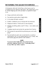
Page 77: ...or difficulty you are having with the instrument Shipment method to Troxler and for return shipment Shipping and billing address not P O Box street address and zip code Telephone number and contact for questions from Troxler Will estimate be required before performing any work on the gauge Payment method credit card account number or purchase order number All U S government agencies city county st...

Page 78: ...ners Grove IL 60515 Fax 630 261 9341 Western Regional Branch Office 11300 Sanders Drive Suite 7 Rancho Cordova CA 95742 Fax 916 631 0541 Southwestern Branch Office 2016 East Randol Mill Road Suite 406 Arlington TX 76011 Fax 817 275 8562 Florida Service Center 2376 Forsyth Road Orlando FL 32807 Fax 407 681 3188 Troxler European Subsidiary Troxler Electronics GmbH Gilchinger Strasse 33 D 82239 Allin...

Page 79: ...Model 2701 B Appendix B 1 B MENU MAP APPENDIX B MENU MAP This appendix provides a map of the various menus in the Model 2701 B PaveTracker Plus control software CONTENTS Menu Map Description B 2 ...

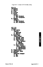
Page 80: ...1 Select 2 View 3 Create 4 Erase Erase 1 One Project 2 All Projects This indicates that by pressing the PROJ key the operator accesses the Project menu The first three items under the Project menu 1 Select 2 View and 3 Create have no submenus The fourth item 4 Erase does have a submenu Press 4 to access the Erase submenu NOTE The menu map contains only the displays that allow or require a keypad s...

Page 81: ... Project 2 All Projects 5 Output Output 1 One Project 2 All Projects SETUP Setup 1 Set Units Units 1 English 2 Metric 2 Date Time Date Time 1 Change Time 2 Change Date 3 Time Format Time Format 1 AM PM 2 24 Hour 4 Date Format Date Format 1 mm dd yyyy 2 dd mm yyyy 3 Temperature 4 Customer Name 5 Beeper External Beeper 1 ON 2 OFF ...

Page 82: ...5 New Entry Method 1 Data Pairs 2 Slope Intercept 6 Disable 7 View 8 Layer Thickness Thickness Option 1 ON 2 OFF TARGET Target 1 Gmb Marshall Gmb MA Value 1 2 Items 1 through 4 represent memory 3 cells used to store Gmb MA values 4 5 New 6 Disable 2 Gmm Voidless Gmm Void Value 1 2 Items 1 through 4 represent memory 3 cells used to store Gmm Void values 4 5 New 6 Disable ...

Page 83: ...Model 2701 B Appendix B 5 B MENU MAP Figure B 1 Model 2701 B Menu Map Continued MODE Mode 1 Continuous 2 Averaging 3 Segregation OFFSET Density Offset 1 Enable 2 Disable 3 Change Offset ...

Page 84: ...Appendix B 6 NOTES ...

Page 85: ...ONS APPENDIX C MODEL 2701 B SPECIFICATIONS This appendix contains gauge and measurement specifications for the Model 2701 B PaveTracker Plus CONTENTS Measurement Specifications C 2 Electrical Specifications C 3 Mechanical Specifications C 4 ...

Page 86: ...avement density in lb ft3 and kg m3 Precision 0 2 lb ft3 3 2 kg m3 at 1 Sigma on reference standard Probe Non nuclear non capacitance measuring field Probing depth Up to 4 45 cm 1 75 in Measurement time 1 second Measurement modes Continuous averaging and segregation ...

Page 87: ...tteries Default Time Before 5 minutes between keypresses Sleep Mode no loss of data or previous status Time Before Automatic 60 minutes of complete inactivity Shutdown Liquid Crystal Display Alphanumeric 4 line 20 characters backlit Keypad 30 key sealed membrane backlit Serial Data Format 8 data bits 1 stop bit No parity Baud rate 9 600 bps Serial Cable Pinout PN 106514 0002 9 pin FEMALE 9 pin FEM...

Page 88: ...n Carrying Case Size 54 0 W 45 1 D 26 7 H cm 21 25 W 17 75 D 10 5 H in Weight Without 4 8 kg 10 5 lb Telescoping Handle Shipping Weight 13 7 kg 30 1 lb Operating Temperature 0 to 70 C Ambient 32 to 158 F Max Test Material Surface 150 C 302 F Temperature Storage Temperature 55 to 85 C 67 to 185 F Humidity 98 noncondensing ...

Page 89: ...3 Backlight 2 5 Battery A 4 Charge A 4 Replace A 5 Beeper external 2 12 Bottom cover disc 1 4 Replacing A 7 C Carrying case 1 4 1 6 Charge batteries A 4 Charger ac 1 6 Cleaning base and top shell A 6 Continuous mode 4 6 Create project 5 4 Customer name 2 11 D Date 2 9 Format 2 10 Date Time 2 8 DC adapter 1 6 Decimal key 2 3 Density offset Determining 3 3 Gyratory sample template 3 3 ...

Page 90: ...fset 3 4 Mix calibration 3 6 Target 2 14 Enter target 2 15 ENTER START key 2 3 Erase projects 5 5 ESC key 2 3 F Format project output 5 6 G Gauge temperature internal A 3 I Inspection 1 7 K Keypad 2 2 L Layer thickness 2 13 5 4 LIGHT key 2 3 2 5 M Measurement Mode 2 16 Specifications C 2 Mechanical specifications C 4 ...

Page 91: ...4 7 Continuous 4 6 Measurement 2 16 Segregation 4 9 Sleep 2 5 C 3 MODE key 2 3 2 16 N NiMH battery pack A 4 NO key 2 3 Numeric keys 2 3 O Offset 3 3 OFFSET key 2 3 Options A 8 Output project data 5 5 P Parts 1 6 Replacement A 8 Printer 1 6 PROJ key 2 3 5 2 Project Create 5 4 Data 5 2 Erase 5 5 Output data 5 5 Output format 5 6 Select 5 2 View 5 3 ...

Page 92: ...n mode 4 9 Select project 5 2 Self test 2 4 Service A 9 Centers iii A 10 Set units 2 8 Setup 2 7 SETUP key 2 3 2 7 Shutdown automatic 2 5 C 3 Sleep mode 2 5 C 3 Slope Intercept 3 9 SPACE key 2 3 Specifications C 1 Electrical C 3 Measurement C 2 Mechanical C 4 Status 2 6 STATUS key 2 3 2 6 Store data 5 8 Averaging mode 5 10 Continuous mode 5 9 Segregation mode 5 10 STORE key 2 3 5 9 5 10 ...

Page 93: ...s 4 5 Target Disable 2 15 Enable 2 14 Enter 2 15 Values 2 14 TARGET key 2 3 2 14 Temperature 2 10 Test site preparation 4 4 Time 2 9 Format 2 10 Troubleshooting A 2 U Units measurement 2 8 Unpacking 1 7 User ID 2 12 V View project 5 3 Y YES key 2 3 ...

Page 94: ...Index 6 NOTES ...

Page 95: ...Model 2701 B Warranty 1 WARRANTY NOTES ...

Page 96: ...er written and signed agreement THERE ARE NO WARRANTIES WHICH EXTEND BEYOND THE DESCRIPTION ON THE FACE HEREOF AND THIS WARRANTY IS EXPRESSLY IN LIEU OF ALL OTHER WARRANTIES EXPRESSED OR IMPLIED AND TROXLER NEITHER ASSUMES NOR AUTHORIZES ANYONE TO ASSUME FOR IT ANY OTHER LIABILITY IN CONNECTION WITH THE SALE OF THE INSTRUMENT THIS WARRANTY SHALL NOT APPLY TO THE INSTRUMENT OR ANY PART THEREOF WHIC...

Reviews: