background image

Model 3430 Plus & 3440 Plus 

Appendix A–13 


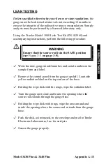
LEAK TESTING 


Unless specified otherwise by your license or state regulations

, the 

gauge must be leak tested at intervals not exceeding 12 months to 
ensure the integrity of the radioactive source encapsulation. Sample 
analysis must be performed by a licensed laboratory only. 


Using the Troxler Model 3880 Leak Test Kit (PN 102868) and 
accompanying instructions, perform the following procedure: 


Write the date, gauge model number, and serial number on the 
sample form and label. 


Remove the control panel from the gauge topshell. Locate the 
yellow radiation label on the top surface of the base. 


Holding the wipe disk with the tongs, wipe the radiation label. 


Turn the gauge on its side and locate the opening where the 
source rod extends through the gauge base. 


Holding the wipe disk with tongs, wipe the area around and 
inside the opening where the source rod extends from the gauge 
base. 


Pack the disk, as instructed, in the envelope and mail to Troxler 
Electronic Laboratories, Inc. for analysis. 


Secure the gauge properly. 

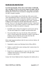
WARNING 

Ensure that the source rod is in the SAFE position 
(see 

Figure 3–3 

on page 3–5). 

  
A. R

AD

IA

TIO

N T

HE

OR


Summary of Contents for 3430 Plus

Page 1: ...th the GPS enabled Note also that the gauge must be positioned such that the GPS receiver can receive signals from the GPS satellites see Appendix I for more information If the GPS does not initialize within 45 minutes contact your Troxler representative Manual of Operation and Instruction Model 3430 Plus 3440 Plus Surface Moisture Density Gauge Troxler Electronic Laboratories Inc 3008 Cornwallis ...

Page 2: ...ms for any purpose without the express written permission of Troxler Electronic Laboratories Inc Fantastic is a trademark of Dow Consumer Products Inc Federal Express is a registered trademark of the Federal Express Corporation 409 is a trademark of the Clorox Company Magnalube G is a registered trademark of Carleton Stuart Corporation Microsoft Excel HyperTerminal Windows and Word are registered ...

Page 3: ...Model 3430 Plus 3440 Plus iii ...

Page 4: ...32807 Fax 407 681 3188 Texas Service Center 2016 East Randol Mill Road Suite 406 Arlington TX 76011 Fax 817 275 8562 Illinois Service Center 1430 Brook Drive Downers Grove IL 60515 Fax 630 261 9341 Northern California Service Center 11300 Sanders Drive Suite 7 Rancho Cordova CA 95742 Fax 916 631 0541 Troxler European Subsidiary Troxler Electronics GmbH Gilchinger Strasse 33 D 82239 Alling nr Munic...

Page 5: ...odel 3430 Plus and 3440 Plus The Model 3430 Plus 3440 Plus Manual of Operation and Instruction contains information on safely using this gauge Also included in this manual are safety warnings gauge setup troubleshooting and general maintenance NOTE Before operating the gauge read this manual carefully If you do not completely understand the sections that cover radiation safety contact your company...

Page 6: ...proper operation KEY Angle brackets and a different typestyle indicate a key or character number or letter to press on the gauge keypad For example Press START means to press the key labeled START DISPLAY A different typestyle is used in text to indicate information or messages displayed on the gauge Diamonds indicate a list of things needed such as equipment or things to know Check marks indicate...

Page 7: ...Model 3430 Plus 3440 Plus vii NOTES ...

Page 8: ...rce Rod Positions 3 5 Daily Inspection 3 6 Turning the Gauge On 3 7 Setup 3 9 CHAPTER 4 USING THE GAUGE Taking a Standard Count 4 2 Preparing a Test Site 4 7 Taking Measurements 4 10 Recall 4 17 CHAPTER 5 SETUP MENU Setup Menu 5 3 Count Time 5 4 Set Units 5 4 Depth Mode 5 4 Stat Test 5 5 Drift Test 5 7 Nomograph 5 10 Precision 5 15 Options 5 17 Battery Status 5 19 Percent Air Voids Soil Mode 5 20 ...

Page 9: ...ut Project 8 7 Set Output Destination 8 10 Deactivate 8 11 Auto Store 8 12 Manual Store 8 14 CHAPTER 9 EXTENDED MENU Extended Menu 9 2 Clock Calendar 9 3 User ID 9 3 Customer Name 9 3 Language 9 4 Source Decay 9 5 Erase Standard Counts 9 6 Low Battery Warning 9 7 Software Reset 9 8 Test Menu 9 9 APPENDIX A RADIATION THEORY AND SAFETY Radiation Theory A 2 Radiation Safety A 5 Regulatory Requirement...

Page 10: ......

Page 11: ...30 APPENDIX D STANDARD COUNT LOG APPENDIX E UNIT CONVERSION Measurement Units E 2 Radiological Units E 2 APPENDIX F GAUGE SPECIFICATIONS Measurement Specifications F 2 Radiological Specifications F 4 Electrical Specifications F 5 Mechanical Specifications F 7 APPENDIX G SPECIAL EUROPEAN CONSIDERATIONS Declaration of Conformity G 2 Safety Warnings G 3 APPENDIX H PRINTING UPLOADING PROJECT DATA Wind...

Page 12: ...lumn Definitions 8 9 A 1 Diagram of an Atom A 2 A 2 Effect of Distance on Exposure A 7 A 3 Cleaning the Tungsten Sliding Block A 12 A 4 Gauge and Transport Case A 18 C 1 Adjusting the Display Contrast C 9 C 2 NiMH Battery Pack and AA Batteries C 11 C 3 Final Assembly Part Numbers 110795_XXXX 3430 Plus and 110800_XXXX 3440 Plus C 19 C 4 Base Assembly Part Number 110015_XXXX C 21 C 5 Scaler Assembly...

Page 13: ...xi LIST OF TABLES Table Title Page 3 1 Key pad Functions 3 4 A 1 Radiation Profile for Gauge A 19 C 1 Error Messages C 6 C 2 Typical Battery Operating Life C 11 I 1 GPS Position Accuracy 4 ...

Page 14: ...Model 3430 Plus 3440 Plus xii NOTES ...

Page 15: ...ons that require an ACCESS CODE This code must be entered before these functions may be used For more information on using the access code refer to Chapter 9 The ACCESS CODE for this gauge is 4708 This page should be removed if the access code is not to be distributed to other parties or users of this gauge ...

Page 16: ...xiv NOTES ...

Page 17: ...f the Troxler Model 3430 Plus and 3440 Plus Surface Moisture Density Gauges and includes a list of the gauge parts and accessories as well as instructions for unpacking and inspecting the gauge CONTENTS Introduction 1 2 Gauge Parts and Accessories 1 5 Unpacking and Inspection 1 7 1 INTRODUCTION ...

Page 18: ...aterials Soil Mode For moisture density determinations in soil and soil stone materials in layers of 4 inches or greater Asphalt Mode For density determinations in asphalt or hardened concrete layers of 4 inches or greater A Nomograph function for density determinations in asphalt layers of less than 4 inches Calibration offsets density moisture and trench to expand measurement possibilities and t...

Page 19: ...be enabled or disabled as desired by the operator The Model 3440 Plus can also be equipped with an optional global positioning system GPS receiver The GPS receiver enables the gauge to store precise GPS coordinates along with the standard date and time stamp for each measurement For more information on the GPS option refer to Appendix I The Model 3430 Plus and 3440 Plus gauges meet or exceed all a...

Page 20: ...uld seek assistance from Troxler an appointed Troxler representative or others designated within the user s organization Additional radiation safety information is available by attending a Troxler Nuclear Gauge Safety Training Course For pricing and availability of these courses visit the Troxler website at www troxlerlabs com TRAINING training shtml or contact your Troxler representative Before o...

Page 21: ...Model 3430 Plus 3440 Plus 1 5 GAUGE PARTS AND ACCESSORIES Figure 1 1 Gauge Parts and Accessories 1 INTRODUCTION ...

Page 22: ...easurements 5 The Extraction Tool provides leverage to remove the drill rod from soil materials 6 The AC Charger and DC Adapter are used to charge the gauge batteries The ac charger accepts 90 220 V ac 50 60 Hz and supplies 12 V dc The dc adapter allows recharging from an automobile cigarette lighter 7 The Transport Case provided with the gauge has been approved as a Type A package Always use this...

Page 23: ... to another location or back to the factory save the box and any packing material For shipping instructions and regulations please see Appendix B Check the shipping case for the following Gauge Reference Standard Block Drill Rod Scraper Plate Drill Rod Guide Extraction Tool AC Charger DC Adapter for a vehicle cigarette lighter Manual of Operation and Instruction Gauge Warranty Source Certificate T...

Page 24: ...t the outside surface for damage Check the lock on the source rod handle and make sure the keys fit Remove the lock release the trigger and check the source rod operation It should move up and down with little effort Return the gauge to the transport case ...

Page 25: ...he Troxler Model 3430 Plus and 3440 Plus Surface Moisture Density Gauges The direct transmission and backscatter modes of operation are illustrated along with an explanation of the cesium 137 source americium 241 beryllium source and detector geometry CONTENTS Density 2 2 Moisture 2 3 Calibration 2 5 Offsets 2 5 2 THEORY OF OPERATION ...

Page 26: ... the probability of these photon collisions This decreases the number of photons that reach the Geiger Mueller G M detectors in the base of the gauge Thus the number of photons reaching the detectors is inversely related to the density of the material the higher the density of the material the fewer the photons that reach the detectors Using the gauge calibration the gauge software converts the G ...

Page 27: ...rectly to the amount of hydrogen in the material Using the gauge calibration the gauge software converts the helium 3 detector counts to a moisture content Note that the helium 3 detector is in the same plane as the Am 241 Be source Therefore moisture measurement is similar to a density measurement taken in backscatter mode as described earlier in this chapter The depth of measurement is defined i...

Page 28: ... The dotted lines indicate the maximum depth of gauge measurement at a given soil moisture content Figure 2 1 Effect of Moisture on Depth of Measurement DepthS 280 0 27 X M 521 kg m3 336 kg m3 96 kg m3 Gauge Measured Moisture Content kg m 3 Gauge Measured Moisture Content pcf DepthE 11 0 17 X M 32 3 pcf 20 8 pcf 5 95 pcf ...

Page 29: ... an offset Perform a density offset if the test material is outside the density range for average soil or if the material composition varies from average soil asphalt Perform a moisture offset if the test material contains hydrogenous materials other than water or materials that absorb neutrons Materials such as cement gypsum coal mica and lime all contain chemically bound hydrogen that will cause...

Page 30: ...2 6 NOTES ...

Page 31: ...cribes the gauge keypad and provides instructions for conducting daily gauge inspections turning the gauge on and setting up the gauge CONTENTS Gauge Illustration 3 2 Control Panel 3 3 Source Rod Positions 3 5 Daily Inspection 3 6 Turning the Gauge On 3 7 Setup 3 9 Setup Menu 3 9 Extended Menu 3 11 Measurement Mode 3 15 Project Function 3 16 Display Backlight 3 16 3 GETTING STARTED ...

Page 32: ...3 2 GAUGE ILLUSTRATION Figure 3 1 illustrates various components of the gauge referred to throughout this chapter and the remainder of the manual Figure 3 1 Gauge Illustration ...

Page 33: ...ows the operator to access the gauge software Troxler designed the keypad for ease of use with large keys and an anti glare coating Pressing a function key activates the function only when the Ready screen is displayed Table 3 1 describes the function of each key POWER SWITCH USB PORT BATTERY CHARGING INDICATOR CHARGER CONNECTOR RS 232 PORT The USB port is included only on the Model 3440 Plus Figu...

Page 34: ...octor or Gmm Voidless density value 6 2 MODE Select the measurement mode Asphalt or Soil 3 15 STD Take a standard count 4 2 SPACE Enter a space LIGHT Manually toggle the LCD and keypad backlights on and off 3 16 YES Respond yes to yes no questions NO Respond no to yes no questions ESC Return the display to the Ready screen without storing or updating the data 0 9 Enter numbers and access menu opti...

Page 35: ...ayer or other materials through which you cannot drill a hole use the backscatter position In the direct transmission positions the source rod extends into a pre drilled hole WARNING The source rod should always be in the SAFE position when the gauge is not in use BS 2 50mm 3 75mm 4 100mm 5 125mm 6 150mm 7 175mm 8 200mm 9 225mm 10 250mm 11 275mm 12 300mm Figure 3 3 Source Rod Positions Maximum Dep...

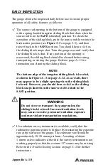
Page 36: ...3 6 DAILY INSPECTION The gauge should be inspected daily before use to ensure proper operation of all safety features Refer to page A 10 for the daily inspection procedure ...

Page 37: ...a 300 second warmup period NOTE To bypass the warmup period press ESC Following the warmup period the gauge displays the Ready screen shown below The operator can access any gauge function from the Ready screen The Ready screen displays the current date and time as well as the current project see Chapter 8 if any NOTE The symbol in the upper right of the display indicates that the GPS option see p...

Page 38: ...such that the GPS receiver can receive signals from the GPS satellites see Appendix I for more information If the GPS does not initialize within 45 minutes contact your Troxler representative NOTE If the gauge display is difficult to read in bright light adjust the contrast as described in the Display Contrast section on page C 9 After 5 hours of no activity the gauge automatically performs a tota...

Page 39: ...ding the measurement units count time measurement mode battery status Gmb Marshall value Proctor value Gmm Voidless density value and measurement depth Use the arrow keys to scroll between the two screens SETUP MENU The gauge provides three different count times to be used in taking measurements The gauge can also display measurement results in either U S units pcf or metric SI units kg m3 or g cm...

Page 40: ...f or metric SI units kg m3 or g cm3 To select the units press 2 at the Setup menu The gauge displays Select the new units using the corresponding number key The gauge displays the new units then returns to the Setup menu Depth Mode The Model 3440 Plus gauge offers two depth modes Automatic and Manual In the Automatic mode the gauge software determines the source rod depth automatically In the Manu...

Page 41: ... store a user ID and customer name These settings are accessed from the Extended menu This menu includes functions that are intended for use by authorized personnel only and requires the use of the access code shown on page xiii To access the Extended menu press 9 at the Setup menu The gauge requests an access code Enter the access code shown on page xiii and press the ENTER START key The gauge di...

Page 42: ... the corresponding numeric key To return to the Extended menu press the ESC key CHANGE TIME To change the time press 1 at the Clock Calendar menu The gauge displays Note that in this example the time is displayed in AM PM format To change the format see the Time Format section on the following page To accept the displayed time press ENTER START To change the time use the numeric keys to enter the ...

Page 43: ...ndar menu TIME FORMAT The gauge can display the time in either AM PM or 24 hour format To select the desired time format press 3 at the Clock Calendar menu The gauge displays Use the numeric keys to select the desired time format The gauge sets the time format and returns to the Clock Calendar menu DATE FORMAT The gauge can display the date in either mm dd yyyy or dd mm yyyy format where mm month ...

Page 44: ...able the alphabetic keys on the gauge When the alphabetic keys are enabled the symbol appears in the upper right of the display as shown above Enter the new user ID and press ENTER START The gauge stores the new user ID and returns to the Extended menu Customer Name The gauge can store a customer name of up to 12 alphanumeric characters To enter a customer name press 3 at the Extended menu The gau...

Page 45: ...nded menu Press ESC twice to return to the Ready screen MEASUREMENT MODE The gauge provides two measurement modes Soil and Asphalt for precise readings on base asphalt concrete soil soil stone aggregate and similar materials The gauge can also be used to determine the density of thin layer overlays using the Nomograph function described on page 5 10 Before taking a measurement select the appropria...

Page 46: ... NOTE The PROJ key is active only when the Ready screen is displayed Chapter 8 provides detailed instructions on the Project function DISPLAY BACKLIGHT Both the Model 3430 Plus and 3440 Plus gauges provide a backlight for the liquid crystal display LCD The backlight can help the operator read the display at night The Model 3440 Plus also features a backlit keypad this feature is not available on t...

Page 47: ...uges Basic use includes taking the daily standard count preparing measurement sites setting the measurement mode and taking measurements CONTENTS Taking a Standard Count 4 2 New Standard Count 4 3 View Standard Counts 4 6 Preparing a Test Site 4 7 Soil Site 4 7 Asphalt Site 4 9 Taking Measurements 4 10 Soil Mode 4 11 Asphalt Mode 4 14 Recall 4 17 4 USING THE GAUGE ...

Page 48: ...meets the following criteria A smooth surface such that the reference standard block does not rock At least 3 meters 10 ft from any large vertical surface At least 10 meters 33 ft from any other radioactive source On asphalt concrete or compacted soil at least 10 centimeters 4 in thick Turn the gauge on At the Ready display press the STD key The gauge displays the last standard counts for density ...

Page 49: ... count site As shown in Figure 4 1 place the gauge on the reference standard block with the right side keypad side of the gauge against the metal butt plate NOTE Ensure that the source rod is in the standard SAFE position and is securely seated by firmly tapping down on the handle of the source rod Figure 4 1 Standard Count Position 4 USING THE GAUGE ...

Page 50: ... the factory calibrated values which are shown on the calibration report sent with the gauge After the first four days of operation or after taking four standard counts compare the daily standard count to the average of the last four counts Acceptable standard count limits are 1 0 for DS density standard and 2 0 for MS moisture standard If the standard count passes record the standard counts then ...

Page 51: ...s than a month since the last standard count but the count was performed correctly and the failure is less than 5 press the YES key If the failure is more than 5 press the NO key Ensure that the gauge is properly positioned on the reference standard block Figure 4 1 Verify that the standard count site meets the criteria listed on page 4 2 Take another standard count and accept it if it fails by le...

Page 52: ...at the bottom of page 4 2 The gauge displays Press YES to view the last four standard counts The gauge displays the last four density standard counts Press YES to view the last four moisture standard counts Press ENTER START to return to the Ready screen Press NO to return to the Ready screen ...

Page 53: ...te back on the surface and press down slightly to level the surface For direct transmission measurements Put the drill rod through the extraction tool and then through one of the guides on the scraper plate Figure 4 2 Wear safety glasses and a radiation dosimeter Place the drill rod assembly on the test site Step on the scraper plate Hammer the drill rod at least 50 mm 2 in deeper than the desired...

Page 54: ...ing from side to side with a hammer Also do not rock the extraction tool from side to side This will distort the hole or cause loose material to fall into the hole Carefully pick up the scraper plate MARK FOR SCRAPER PLATE CENTER EDGE MARKS MARK FOR DRILL ROD CENTER METHOD 1 METHOD 2 Figure 4 3 Marking the Test Area SCRAPER PLATE SCRAPER PLATE ...

Page 55: ... the voids on open mixes with sand or cement The gauge base must rest on the asphalt not the fill material Ensure that the gauge does not rock To ensure accurate readings the gauge base must be completely in contact with the test material If the gauge rocks then find a more suitable test site If taking a measurement around a core the gauge may be moved a few inches away from the core to level it 4...

Page 56: ...ge 4 2 Note that some states may require that a standard count be taken more frequently than once per day The gauge can store measurement results in files memory locations called projects For information on creating and activating project files refer to Chapter 8 Upon completion of a measurement the results can be stored either automatically by enabling the Auto Store function see page 8 12 or man...

Page 57: ... should hear a click when the source rod locks into position Gently slide the gauge to the right towards the keypad so the source rod makes contact with the wall of the hole Press the ENTER START key In the Manual depth mode see page 5 4 the gauge prompts for the source rod depth Enter the source rod depth using the number keys For example with the source rod in the backscatter position press 0 Th...

Page 58: ...he GPS option and is shown only when this option is enabled The latitude and longitude values denote the quality of the location fix If WAAS information is available during a gauge measurement the latitude and longitude will be displayed to the nearest hundredth 1 100 of a second If a GPS location is determined but the WAAS information is unavailable the latitude and longitude will be displayed to...

Page 59: ...Auto Store function is not enabled Press STORE to store the results Follow the prompts to enter location information and or notes For more information on storing results manually see page 8 14 Press ESC to return to the Ready screen without storing the results Note that until another measurement has been taken the results can be recalled as described on page 4 17 and stored later Lift the gauge fr...

Page 60: ...SAFE position Release the trigger Gently push the handle down to lock the source rod into position You should hear a click when the source rod locks into position Press the START key In the Manual depth mode see page 5 4 the gauge prompts for the source rod depth Enter the source rod depth using the number keys For example with the source rod in the backscatter position press 0 Then press ENTER ST...

Page 61: ...ith the GPS option and is shown only when this option is enabled The latitude and longitude values denote the quality of the location fix If WAAS information is available during a gauge measurement the latitude and longitude will be displayed to the nearest hundredth 1 100 of a second If a GPS location is determined but the WAAS information is unavailable the latitude and longitude will be display...

Page 62: ...mpts to enter location information and or a note If a project is active but the Auto Store function is not enabled Press STORE to store the results Follow the prompts to enter location information and or notes For more information on storing results manually see page 8 14 Press ESC to return to the Ready screen without storing the results Note that until another measurement has been taken the resu...

Page 63: ...t press the RECALL key from the Ready screen To return to the Ready screen press the ENTER START key NOTE The RECALL key is active only when the Ready screen is displayed NOTE The Recall function can also be used to view the gauge counts from the most recent measurement 4 USING THE GAUGE ...

Page 64: ...4 NOTES ...

Page 65: ...ers CONTENTS Setup Menu 5 3 Count Time 5 4 Set Units 5 4 Depth Mode 5 4 Stat Test 5 5 Taking a Stat Test 5 5 Reviewing the Stat Test 5 6 Printing the Stat Test 5 6 Drift Test 5 7 Taking a Drift Test 5 8 Reviewing the Drift Test 5 9 Printing the Drift Test 5 9 Nomograph 5 10 Enable Nomograph 5 11 Disable Nomograph 5 11 Change View Nomograph Data 5 11 Taking Nomograph Measurements 5 14 5 SETUP MENU ...

Page 66: ...5 2 CONTENTS Continued Precision 5 15 Options 5 17 External Beeper 5 17 GPS Option 5 17 Battery Status 5 19 Percent Air Voids Soil Mode 5 20 ...

Page 67: ...TUP key The gauge displays NOTE The SETUP key is active only when the Ready screen is displayed Use the arrows keys to scroll through the menu screens To select a menu option use the number key that corresponds to that option The remainder of this section provides details on the functions available from the Setup menu 5 SETUP MENU ...

Page 68: ... 9 SET UNITS The gauge can display measurement results in either U S units pcf or metric SI units kg m3 or g cm3 The Set Units function is described on page 3 10 DEPTH MODE The Model 3440 Plus gauge offers two depth modes Automatic and Manual The Depth Mode function allows the operator to set the depth mode as described on page 3 10 ...

Page 69: ...al test If the second test fails contact the nearest Troxler service center for assistance For a list of Troxler and authorized Troxler service centers refer to page iii of this manual or visit the Troxler website at www troxlerlabs com SERVICES services shtml To access the Stat Test function press 4 at the Setup menu The gauge displays the Stat Test menu To select a menu option press the correspo...

Page 70: ...s shown above Press ENTER START to view the results of the moisture stat test Follow the prompts to scroll through the results PRINTING THE STAT TEST To print the results of the last stat test to a serial printer or computer via the gauge s 9 pin serial port press 3 at the Stat Test menu shown on page 5 5 The gauge prompts the operator to connect the printer to the gauge Connect a serial cable to ...

Page 71: ...nd take an additional test If the second test fails contact the nearest Troxler service center for assistance For a list of Troxler and authorized Troxler service centers refer to page iii of this manual or visit the Troxler website at www troxlerlabs com SERVICES services shtml NOTE The drift test consists of five 4 minute counts whereas the stat test consists of twenty 1 minute counts Therefore ...

Page 72: ...NOTE If it has been less than three hours or more than eight hours since the last stat test the gauge displays an error message Press ENTER START to return to the Setup menu The gauge displays the progress of the drift test five 4 minute counts Upon completion of the counts the gauge displays the results of the density drift test including an indication of whether the test passed or failed Press E...

Page 73: ...results of the last drift test to a serial printer or computer via the gauge s 9 pin serial port press 3 at the Drift Test menu shown on page 5 7 The gauge prompts the operator to connect the printer to the gauge Connect a serial cable to the gauge s serial port Ensure that the serial cable meets the pinout shown on page F 6 An optional serial cable PN 113128 is available from Troxler Connect the ...

Page 74: ...than 3 in 7 5 cm and scattering back to the gauge These backscattered photons from the underlying material will adversely influence the reading Obtaining an accurate overlay density with the Nomograph method requires that the density of the bottom layer and the thickness of the top layer be determined The simplest method of determining the density of the bottom layer is to take a nuclear gauge mea...

Page 75: ...auge disables the function displays a brief confirmation message and returns to the Setup menu CHANGE VIEW NOMOGRAPH DATA To change or view the Nomograph data press 3 at the Nomograph menu shown on page 5 10 The gauge displays To return to the Setup menu without changing the Nomograph data press NO To change the Nomograph data press YES The gauge displays The wet density of the underlying or base ...

Page 76: ...e displays Enter the wet density of the bottom layer The gauge enables the Nomograph function using the entered values displays a brief confirmation message and returns to the Setup menu Entering Density Using Gauge Measurements Bottom density values may be obtained by using the gauge to record up to 20 actual measurements To enter the density using this method press 2 at the Select Method of Ente...

Page 77: ...e displays After counting down to zero the gauge displays If more than one reading is to be taken move the gauge to the next location and press ENTER START The gauge will repeat the above sequence for each reading When all the readings are completed the display will be Press ENTER START to continue The gauge enables the Nomograph function displays a brief confirmation message and returns to the Se...

Page 78: ...ress ENTER START to begin the test The gauge displays After counting down to zero the display is This test may be stored as any other test measurement The recall function and or printout will show that the Nomograph function was used NOTE The Nomograph function should be disabled before taking any measurements not requiring this function ...

Page 79: ...within range and the time required to calculate the required result does not exceed 60 minutes the following procedure can usually produce the required results To execute the Precision function first ensure that the gauge is in the correct mode Soil or Asphalt Press 7 from the Setup menu shown on page 5 3 The gauge displays Enter the desired precision and press ENTER START The gauge displays If th...

Page 80: ...his operation and return to the Setup menu press ESC To continue with the Precision function press ENTER START After counting down the display will be For Soil mode For Asphalt mode NOTE If the required precision cannot be reached in 60 minutes the gauge halts the count and displays a warning message ...

Page 81: ...s desired To toggle the external beeper on or off press 1 on the Options menu shown above GPS OPTION The Model 3440 Plus gauge can also be equipped with an optional global positioning system GPS receiver The GPS receiver enables the gauge to store precise GPS coordinates along with the standard date and time stamp for each measurement To toggle the GPS function on or off press 2 on the Options men...

Page 82: ...stances initialization may take as long as 30 to 45 minutes from the time the gauge is powered on with the GPS enabled Note also that the gauge must be positioned such that the GPS receiver can receive signals from the GPS satellites see Appendix I for more information If the GPS does not initialize within 45 minutes contact your Troxler representative ...

Page 83: ...e NiMH batteries the charge percentage and the status of the charge calibration To access this function press 9 at the Setup menu shown on page 5 3 For more information see the Battery Status section on page C 10 For more information on the charge calibration see page C 12 5 SETUP MENU ...

Page 84: ...e of the display For optimum results use a specific gravity value that is appropriate for the material being measured To enable the current specific gravity value press 1 The gauge enables the value displays a brief confirmation message and returns to the Setup menu To disable the current specific gravity press 2 The gauge disables the value displays a brief confirmation message and returns to the...

Page 85: ...ll values four different Proctor values and four voidless density target values The gauge uses the target values to determine the percent compaction after it has determined the density of the test material CONTENTS Target Menu 6 2 Target Values 6 3 Enable a Target Value 6 3 Store a New Target Value 6 4 Disable the Target Value 6 4 6 TARGET MENU ...

Page 86: ...boratory tests When enabled the voidless density is used to determine the percent air voids The gauge uses the Proctor value to calculate the compaction level when taking measurements in the Soil mode The Target function enables the operator to enter and store a new target value as well as to enable or disable a target value stored in memory To access the Target menu press the TARGET key The gauge...

Page 87: ...ponds to that target value as shown on the Target menu see page 6 2 For example to edit the Gmb Marshall value press 1 The gauge displays the selected Target Value menu The menu for the Gmb Marshall value is The Target Value menu shows the target values stored in memory if any and the New and Disable options ENABLE A TARGET VALUE To enable a target value displayed on the Target Value menu press th...

Page 88: ...key The gauge displays The gauge can store the value in one of four memory cells Storing a new value in a cell erases the old value Use the number keys to store the value This will replace any stored values that were previously associated with the memory cell The gauge stores the target value enables it for use and returns to the Ready screen DISABLE THE TARGET VALUE To disable the target value pr...

Page 89: ... gauge is to be used on materials outside of the typical operating range the operator can adjust the gauge using an offset This chapter explains how to adjust gauge readings using offsets CONTENTS Offset Menu 7 2 Density Offset 7 3 Moisture Offset 7 4 Enable a Stored Moisture Offset 7 4 Enter a New Moisture Offset 7 4 Disable the Moisture Offset 7 7 Trench Offset 7 8 7 CALIBRATION OFFSETS ...

Page 90: ...gen rich materials are cement gypsum coal mica and lime The moisture offset for soils containing these materials is a negative value If the material is high in neutron absorbing material such as boron cadmium or chlorine the offset must be a positive value Perform a trench offset before taking measurements inside a trench or close vertical structures Vertical structures scatter neutrons and gamma ...

Page 91: ...d density offset press 1 The gauge enables the offset displays a brief confirmation message and returns to the Ready screen To disable the density offset press 2 The gauge disables the offset displays a brief confirmation message and returns to the Ready screen NOTE The density offset is also disabled when the gauge is turned off To enter a new density offset press 3 The gauge prompts for the dens...

Page 92: ...e offset values stored in memory if any and the New and Disable options ENABLE A STORED MOISTURE OFFSET To enable a moisture offset value displayed on the Moisture Offset menu press the number key that corresponds to that value The gauge enables the moisture offset value and returns to the Ready screen ENTER A NEW MOISTURE OFFSET A new moisture offset may be entered either manually using the keypa...

Page 93: ...late the average moisture of the readings to determine the gauge moisture content To enter the moisture offset manually press 1 at the Select Offset Source menu shown on page 7 4 The gauge request the true moisture value as shown Enter the true moisture value and press ENTER START The gauge requests the gauge moisture value as shown Enter the gauge moisture value and press ENTER START The gauge ca...

Page 94: ...t enables it for use and returns to the Ready screen Gauge Derived Moisture Offset To allow the gauge to derive the moisture offset the operator must determine the true moisture content of a sample taken at the measurement site using standard laboratory methods for example oven drying and so on then take readings with the gauge To use this method of determining the moisture offset press 2 at the S...

Page 95: ...t for later use press YES The gauge displays The gauge can store the value in one of four memory cells Storing a new value in a cell erases the old value Use the number keys to store the value This will replace any stored values that were previously associated with the memory cell The gauge stores the moisture offset enables it for use and returns to the Ready screen DISABLE THE MOISTURE OFFSET To...

Page 96: ...values NOTE Before determining a new trench offset ensure that a standard count has been performed recently outside the trench To access the Trench Offset menu press 3 at the Offset menu shown on page 7 2 The gauge displays The gauge displays the current offset values on the second line To enable the displayed trench offset press 1 The gauge enables the offset displays a brief confirmation message...

Page 97: ... distance from the wall as the test measurements Place the gauge on the standard block in this position set the source rod to the SAFE position and press ENTER START The gauge performs a trench count calculates the trench moisture and density offset values enables the trench offset and returns to the Ready screen 7 CALIBRATION OFFSETS ...

Page 98: ...7 NOTES ...

Page 99: ...equent measurements can then be stored under these project names This chapter describes how to handle project data CONTENTS Project Menu 8 2 Select 8 3 View 8 4 Create a Project 8 5 Erase Projects 8 6 Output Project 8 7 Set Output Destination 8 10 Deactivate 8 11 Auto Store 8 12 Active Project Selected 8 12 No Project Data 8 13 No Project Selected 8 13 Manual Store 8 14 8 PROJECT DATA ...

Page 100: ...ect make an existing project active so that additional data may be added to it view project data create a new project erase projects output project data to the selected destination via the serial or USB port deactivate a project and enable the Auto Store function To access the Projects menu press PROJ The gauge displays NOTE The PROJ key is active only when the Ready screenis displayed Use the arr...

Page 101: ...turn to the Projects menu and create a project as described on page 8 5 If a project has been created the gauge displays Use the arrow keys to scroll through the names of the existing projects When the desired project is displayed press ENTER START to select it as active The gauge sets the selected project as active briefly displays a confirmation message and returns to the Projects menu 8 PROJECT...

Page 102: ...ored in a project file press 2 at the Projects menu The gauge displays Use the arrow keys to scroll through the project names Press ENTER START when the gauge displays the desired project name If any measurement data has been stored in the selected project file the gauge displays the data for the first measurement Six screens of information are displayed for each measurement Use the up and down ar...

Page 103: ...play as shown above Enter the project name up to twelve alphanumeric characters and press the ENTER START key The gauge displays To save the new project name without activating it press NO The gauge saves the new project briefly displays the name of the active project if any and returns to the Projects menu To save the new project name and activate the project press YES The gauge enables the new p...

Page 104: ...ted the gauge displays Use the arrow keys to scroll through the project names displayed on the first line When the gauge displays the desired project press ENTER START At the Are you sure prompt press the YES key The gauge erases the project and returns to the Projects menu To erase all projects press 2 at the Erase menu At the Are You Sure prompt press the YES key The gauge erases all the project...

Page 105: ...nect the serial cable to the printer or computer serial port NOTE To upload data to a computer use the HyperTerminal application available from the Windows Accessories menu This application can be used to transfer data from the gauge to the computer For more information on setting up HyperTerminal to communicate with the gauge see Appendix H To output project data to a USB printer via the USB port...

Page 106: ...nformation contained in each column of the spreadsheet Press 1 or 2 to select the desired output format The gauge displays From this menu the gauge can print or upload either a single project or all projects To output a single project press 1 The gauge displays Use the arrow keys to scroll through the project names displayed on the first line When the gauge displays the desired project press ENTER...

Page 107: ...Soil Q Voids Ratio R Latitude S Longitude T Center Line Side U Center Line Distance V Gmb Target W Gmm Target X Proctor Target Y Specific Gravity Z Bottom Layer Density AA Top Layer Thickness AB Density Offset AC Moisture Offset AD Trench Density Offset AE Trench Moisture Offset AF Model Number AG Serial Number AH Depth AI Time Count Time AJ Density Standard Count AK Moisture Standard Count AL Den...

Page 108: ... a device with maximum dimensions of 10 mm 0 40 in high by 29 mm 0 79 in wide NOTE A list of USB devices that are compatible with the gauge is available on the following page of the Troxler website www troxlerlabs com PRODUCTS PRODLIT otherlit shtml To select the output destination press 6 at the Projects menu shown on page 8 2 The gauge displays Use the numeric keys to select the desired output d...

Page 109: ...t project without selecting a different one as active press 7 at the Projects menu shown on page 8 2 The gauge deactivates the current project displays a brief confirmation message and returns to the Projects menu Press ESC to return to the Ready screen 8 PROJECT DATA ...

Page 110: ...ss 8 at the Projects menu shown on page 8 2 The gauge displays To return to the Projects menu without changing the Auto Store status press ESC To turn the Auto Store function on press 1 To turn the Auto Store function off press 2 The gauge updates the Auto Store status displays a brief confirmation message and returns to the Projects menu ACTIVE PROJECT SELECTED If the operator attempts to enable ...

Page 111: ...u NO PROJECT SELECTED If the operator attempts to enable the Auto Store function and one or more projects have been created but no project has been selected as active the gauge displays To select an existing project press 1 The gauge displays the screens required to select a project as described on page 8 3 After the project is selected the gauge sets the project as active briefly displays the con...

Page 112: ... No active project then returns to the Ready screen NOTE The STORE key is active only when measurement data is displayed Measurement data is displayed at the end of a reading or the most recent test results can be displayed using the RECALL key see page 4 17 For each measurement the gauge can store a location description of up to 12 characters as well as a note of up to 15 characters For an Asphal...

Page 113: ...ins functions that are intended for use by authorized personnel only This chapter describes these functions CONTENTS Extended Menu 9 2 Clock Calendar 9 3 User ID 9 3 Customer Name 9 3 Language 9 4 Source Decay 9 5 Erase Standard Counts 9 6 Low Battery Warning 9 7 Software Reset 9 8 Test Menu 9 9 9 EXTENDED MENU ...

Page 114: ...lay the Setup menu then press 9 The gauge requests an access code Enter the access code shown on page xiii and press the ENTER START key The gauge displays the Extended menu Use the up and down arrows to scroll between the menu options To select a menu option press the corresponding numeric key To return to the Setup menu press the ESC key ...

Page 115: ...he display format for each This function is described on page 3 12 USER ID The gauge can store a three character user ID with each measurement To enter or change the user ID refer to page 3 14 CUSTOMER NAME The gauge can store a customer name of up to 12 characters To enter or change the customer name refer to page 3 14 9 EXTENDED MENU ...

Page 116: ...lish Spanish German and French To access the Language function press 4 at the Extended menu shown on page 9 1 The gauge displays Use the up and down arrows to scroll between the menu options To select the desired language press the corresponding numeric key To return to the Extended menu press the ESC key ...

Page 117: ...on allows the operator to view how the decrease in the radiation intensity of the source affects gauge density measurements It displays the actual density standard count the predicted standard count and the percent difference between the two sets of counts The gauge calculates the predicted standard count based upon the density standard count at the time the gauge was calibrated and the number of ...

Page 118: ...uge memory To execute the Erase Standard Counts function press 6 at the Extended menu shown on page 9 1 The gauge displays To return to the Extended menu without erasing the standard counts stored in memory press NO To erase all the standard counts press YES The gauge erases the standard counts stored in memory and returns to the Extended menu ...

Page 119: ...auge has approximately three hours of battery operating life left or less if the backlight is used If the gauge is equipped with a GPS unit available only on Model 3440 Plus gauges the remaining battery operating life will be approximately one hour The Low Battery Warning function enables the operator to select how early or late the low battery warning is displayed An early setting provides more t...

Page 120: ... not affect the calibration constants gauge serial number clock and calendar settings or projects stored in the gauge memory To access this function press 7 at the Extended menu shown on page 9 1 The gauge displays To return to the Extended menu without resetting system variables press NO To reset system variables to default values press YES The gauge resets the system variables and returns to the...

Page 121: ...Model 3430 Plus 3440 Plus 9 9 TEST MENU NOTE The functions available from the Test Menu are to be used by qualified service personnel only 9 EXTENDED MENU ...

Page 122: ...9 NOTES ...

Page 123: ...p and use of the gauge as well as a listing of radiation safety related warnings and cautions is included CONTENTS Radiation Theory A 2 Atomic Structure A 2 Radioactivity A 3 Types of Radiation A 4 Radiation Safety A 5 Radiation Dose A 5 Limiting Exposure A 6 Personnel Monitoring A 8 Source Encapsulation A 8 Source Rod Inspection A 9 Daily Inspection A 10 Cleaning the Tungsten Block A 11 Leak Test...

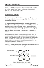
Page 124: ...ces the number of electrons in an atom equals the number of protons The number of protons in the atom is called the atomic number Z A chemical element consists of all atoms having the same atomic number The number of protons plus neutrons in the nucleus is called the atomic mass A Atoms of a given chemical element can exist in slightly different variants called isotopes that have different atomic ...

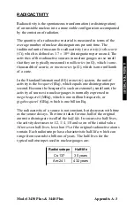
Page 125: ...I or metric system the unit of activity is the becquerel Bq which equals one disintegration per second Because the becquerel is such an extremely small unit the activity of sources in nuclear gauges is normally expressed in megabecquerel MBq which is one million becquerels or gigabecquerel GBq which is one billion Bq The radioactivity of a source is not constant but decreases with time as the sour...

Page 126: ...ves and visible light Photons have no mass or electrical charge and travel at the speed of light Gamma rays are energetic and penetrating Dense materials such as lead tungsten and so on provide the best shielding against gamma radiation Neutrons are a form of particulate radiation but unlike alpha and beta particles they have no electrical charge This makes neutron radiation very penetrating Fast ...

Page 127: ...diation dose is expressed in smaller units called millirem mrem where 1 rem 1000 mrem The risk of injury from radiation is generally related to the total radiation dose received over a period of time It is also related to the dose rate which is the amount of dose received per unit time The same amount of radiation received over a long period months to years is much less hazardous than if received ...

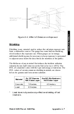
Page 128: ...e Distance Shielding Time The simplest way to reduce exposure is to minimize the time spent around a radioactive source If the time spent near a source is cut in half then the exposure is halved all other factors remaining constant Distance Distance is another effective means to reduce radiation exposure A formula known as the inverse square law relates the radiation exposure rate to distance Figu...

Page 129: ...cent areas below the dose limits for members of the public The thickness of any material that reduces the incident radiation intensity by one half is known as the half value layer HVL The HVL of a material varies with the type and energy of radiation The HVL values of certain common shielding materials are shown below for gamma and fast neutron radiation Material Cs 137 Gamma Half Value Layer Am 2...

Page 130: ... as Atomic Radiation Workers In such cases the general public dose limit of 500 mrem year applies Users may not be required to wear a dosimeter To establish the personnel monitoring requirements for your application consult the conditions of your radioisotope license and the CNSC regulatory document R91 Monitoring and Dose Recording for the Individual SOURCE ENCAPSULATION The neutron Am 241 Be and...

Page 131: ...r if a survey meter is not available perform a visual inspection of the source rod tip as follows to confirm its integrity 1 Extend the source rod just far enough to see the source rod tip The tip should appear flat to slightly rounded and smooth 2 Stay at least three feet away from the tip of the unshielded source rod and complete the inspection as quickly as possible to minimize exposure the dos...

Page 132: ...cleaning the sliding block NOTE The bottom edge of the tungsten sliding block is beveled as shown in Figure A 3 on page A 12 As a result there may appear to be a slight opening when the sliding block is closed However you should hear a click as the sliding block snaps shut when the source rod is raised to the SAFE position If a radiation survey instrument is available verify that the radioactive g...

Page 133: ...e nearest Troxler Service Center For a list of Troxler and authorized Troxler service centers refer to page iii of this manual or visit the Troxler website at www troxlerlabs com SERVICES services shtml The tungsten sliding block may require cleaning if the source rod becomes difficult to lower into the measure position or if a click is not heard when the source rod is raised to the SAFE shielded ...

Page 134: ...side of the gauge Paying close attention to the position of the sliding block remove the block Using a stiff brush or rag soaked in alcohol clean the sliding block and the cavity Re install the sliding block with the angled side up Apply a light coating of Magnalube G paste to the top angled surfaceof the sliding block Re install the bottom plate Do not over tighten screws Ensure that the source r...

Page 135: ...umber on the sample form and label Remove the control panel from the gauge topshell Locate the yellow radiation label on the top surface of the base Holding the wipe disk with the tongs wipe the radiation label Turn the gauge on its side and locate the opening where the source rod extends through the gauge base Holding the wipe disk with tongs wipe the area around and inside the opening where the ...

Page 136: ... be downloaded from the Troxler website www troxlerlabs com To purchase a nuclear gauge in Canada an owner must obtain a radioisotope license from the Canadian Nuclear Safety Commission CNSC The owner should obtain copies of the CNSC Regulations and the Transportation of Dangerous Goods Act and Regulations For other countries please consult your local regulatory agency TRAINING In the United State...

Page 137: ...iation Safety Officer RSO The gauge owner should complete the emergency contact information on the lines furnished below Note that company refers to the gauge owner s company not Troxler Electronic Laboratories This information should be readily available to the gauge operator at all times If a gauge is damaged then follow the steps below 1 Locate the gauge and or sources 2 Do not touch or move th...

Page 138: ...me and location of the accident b The gauge model and serial number c The nature of the accident d The location and condition of the gauge and or source e The dose rate at 3 ft 1 m from the gauge 9 If you are unable to reach the RSO then call your regulatory agency name and number given at the beginning of this section 10 Follow the instructions of the RSO The RSO may need to report the incident t...

Page 139: ...ion look at the bottom of the gauge to verify that the tungsten sliding block is completely closed If the gauge base opening is not completely closed by the sliding block the sliding block may require cleaning Refer to page A 11 for cleaning instructions Do not store or transport the gauge unless the sliding block is completely closed Increased radiation levels may cause excessive personnel radiat...

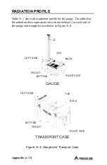
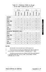
Page 140: ...gauge The table lists the radiation dose equivalent rates in mrem hour for each side of the gauge and transport case shown in Figure A 4 LEFT SIDE TOP BACK FRONT BOTTOM RIGHT SIDE GAUGE LEFT SIDE TOP BACK BOTTOM FRONT TRANSPORT CASE RIGHT SIDE Figure A 4 Gauge and Transport Case ...

Page 141: ... 0 1 0 05 0 1 GAUGE IN TRANSPORT CASE Back 2 0 0 3 2 3 0 7 0 09 0 8 0 1 0 05 0 2 Right Side 7 5 1 8 5 0 7 0 2 0 9 0 1 0 05 0 1 Front 4 0 0 3 4 3 0 8 0 1 0 9 0 1 0 05 0 2 Left Side 0 4 0 09 0 4 0 1 0 05 0 2 0 1 0 05 0 1 Top 9 0 0 2 9 2 1 1 0 1 1 2 0 2 0 05 0 2 Bottom 3 1 0 3 3 4 1 3 0 09 1 4 0 3 0 05 0 3 NOTES 1 All radiation measurements are in millirem per hour 2 Gamma measurements were obtained ...

Page 142: ...Appendix A 20 NOTES ...

Page 143: ...ternational Atomic Energy Agency IAEA The IAEA recommendations have been codified in the International Air Transport Association IATA Dangerous Goods Regulations International customers should consult their local government or licensing authority for applicable regulations CONTENTS U S Shipping Requirements B 2 Accident Notification Requirements B 3 Hazmat Training B 3 Canadian Shipping Requiremen...

Page 144: ...ebsite www troxlerlabs com A copy of the results of the Type A package testing must be kept on file Hazmat employee training records must be kept on file An Emergency Response Information document must be in the vehicle and immediately accessible to the driver A properly completed bill of lading must be in the vehicle and immediately accessible to the driver The shipping papers must include a 24 h...

Page 145: ...t that occurs during the course of transportation including loading unloading and temporary storage in which fire breakage spillage or suspected contamination occurs involving shipment of radioactive materials HAZMAT TRAINING The U S DOT regulations require every hazmat employer to train test certify and maintain records for each hazmat employee Hazmat training applies to anyone who transports or ...

Page 146: ...s Regulations TPRM apply any time a nuclear device used in commerce is transported by any means in Canada For training and accident notification requirements consult the Transportation Of Dangerous Goods Regulations For further information on transporting a nuclear device contact the transportation section of the Canadian Nuclear Safety Commission CNSC ...

Page 147: ...ww troxlerlabs com SERVICES services shtml CONTENTS Troubleshooting C 2 Error Messages C 6 Display Contrast C 9 Batteries C 10 Battery Status C 10 Charging the NiMH Batteries C 12 Charge Calibration C 12 Replacing the NiMH Battery Pack C 13 Installing and Using Alkaline Batteries C 14 Mechanical Maintenance C 15 Cleaning the Base and Top Shell C 15 Lubricating the Source Rod C 16 Replacing Gasket ...

Page 148: ...ce around gauge Check that any sources are at least 10 m 33 ft away Ensure the source rod handle is fully latched in the SAFE shielded position Check that the gauge is positioned correctly on the reference standard block see Figure 4 1 on page 4 3 Perform the standard count again If the standard count still fails contact the nearest Troxler Service Center NO DENSITY READINGS The most likely reason...

Page 149: ...nt time a four minute count will give the highest precision with a repeatability of 1 pcf on repeated tests performed without moving the gauge Erratic density readings may be caused by a dirty tungsten sliding block Clean the sliding block see page A 11 Perform a stat test see page 5 5 If test passes proceed with job If test fails repeat two more times If test fails two out of three times contact ...

Page 150: ... board must be replaced contact the nearest Troxler Service Center Check gauge for water damage If the gauge is wet dry the gauge interior with hair dryer on low heat for 3 hours Check that the calibration constants are valid Ensure that the measurement depth displayed by the gauge corresponds to the actual source rod depth GAUGE TURNS OFF AFTER IT IS TURNED ON The gauge may be wet If the gauge is...

Page 151: ...a c outlet and the dc output 12 V dc using a voltmeter on the proper setting Check that you are using the correct charger The ac charger may be defective To check use the dc adapter to charge the batteries SATISFACTORY COUNTS BUT RESULTS ARE IN ERROR Ensure that the measurement depth displayed by the gauge corresponds to the actual source rod depth Check that the calibration constants are valid Ch...

Page 152: ...en Printer An error occurred when trying to communicate with a USB printer Check that the printer is powered on and is properly connected to the USB port Ensure that the printer is compatible with the gauge A list of compatible USB devices is available at www troxlerlabs com PRODU CTS PRODLIT otherlit shtml Cannot Write to the File An error occurred when attempting to store data to a USB flash dri...

Page 153: ... pcf Invalid Access Code Operator entered an invalid access code Enter the correct access code see page xiii Invalid Depth The source rod is not at a valid depth when starting a measurement Ensure the source rod position is at a valid depth when starting a measurement Contact the nearest Troxler Service Center see page iii Low Battery Gauge Shutting Down Turn off Charge The following three items a...

Page 154: ... When using the Nomograph function see page 5 10 the overlay thickness value must be between 0 and 10 in The operator has entered a value outside this range Enter an overlay thickness value between 0 and 10 in Warning Time to Reach Precision too high When using the Precision function see page 5 15 the time required to reach the selected precision value exceeds 60 minutes Enter a different precisio...

Page 155: ...t forward As shown in Figure C 1 an adjustment potentiometer for the display contrast is located inside an access hole in the back panel of the control unit Using a small screwdriver adjust the potentiometer to obtain the desired display contrast Gently place the control unit inside the gauge and tighten the four captive screws in the corners of the keypad Figure C 1 Adjusting the Display Contrast...

Page 156: ... charged NiMH battery pack and a set of new AA alkaline batteries As shown in the table the typical battery operating life is impacted by the use of the backlight and whether or not the gauge is equipped with a GPS unit available only on the Model 3440 Plus BATTERY STATUS The Battery Status function displays the voltage and charge status of the NiMH batteries as well as the status GOOD or BAD of t...

Page 157: ...IES 5 Figure C 2 NiMH Battery Pack and AA Batteries Table C 2 Typical Battery Operating Life Backlight GPS Installed Typical Life NiMH Battery Pack Typical Life AA Batteries Off No 110 hours 55 hours Off Yes 35 hours 18 hours On Yes 15 hours 8 hours On No 25 hours 13 hours From full charge Model 3430 Plus 3440 Plus Appendix C 11 C TROUBLESHOOTING ...

Page 158: ...nd store for later use NOTE The battery select switch see Figure C 2 must be in the RECHARGEABLE position to charge the NiMH batteries CHARGE CALIBRATION If the Battery Status display see page C 11 shows that the charge calibration is BAD recalibrate as follows Recharge the batteries as described above When the battery charging indicator goes out press STATUS and ensure that the battery charge is ...

Page 159: ...op shell to the gauge base Clean the screws and set them aside Carefully remove the gauge top shell and slide it up out of the way To keep the top shell out of the way tie it to the handle Unplug the battery cable from the battery connection on the t o p circuit board see Figure C 2 Gently squeeze the connector to disconnect Remove the two battery pack screws and set them aside Remove the old NiMH...

Page 160: ...captive screws on the control unit Carefully lift the control unit from the gauge Unplug the ribbon cable from the control unit Install five standard AA alkaline batteries into the battery holder see Figure C 2 Set the battery select switch to the ALKALINE position Plug the ribbon cable into the control unit Attach the control unit to the gauge with the four captive screws ...

Page 161: ...ell may be cleaned with mild low alkaline soap and water Other approved cleaning substances include methyl isopropyl or isobutyl alcohols A cloth dampened with kerosene or diesel fuel may be used to remove heavy soils Avoid prolonged exposure and do not soak CAUTION EUROPEAN COUNTRIES Do not separate the control unit from the base Doing so will result in non compliance with EMC directive Call your...

Page 162: ...rod tower Remove the control unit from the gauge by loosening the four captive screws that secure the control unit to the top shell Lift the control unit out of the gauge and disconnect the ribbon cable Locate the grease fitting at the bottom of the source rod tower Using a standard 16 oz grease gun loaded with a Magnalube G cartridge apply five shots of lubricant to the grease fitting Re assemble...

Page 163: ... control panel gasket part number 110841 loosen the four captive screws that attach the control unit keypad to the top shell Carefully lift the control unit from the top shell and detach the ribbon cable Gently peel the old gasket from the panel and replace it with a new gasket Reconnect the ribbon cable and reinstall the control unit To replace the top shell O ring part number 110899 remove the s...

Page 164: ...his section provides drawings and parts list for the gauge final assembly base assembly scaler assembly control unit and baseboard assembly NOTE For each parts list match the Item number with the correct part in the accompanying figure ...

Page 165: ...Assembly Part Numbers 110795_XXXX 3430 Plus and 110800_XXXX 3440 Plus 20 34 12 16 11 10 2 27 31 35 37 38 DEPTH STRIP NOT USED IN 3430 PLUS 17 25 32 39 14 26 8 21 13 22 23 24 4 18 19 28 29 30 9 3 13 36 7 5 13 6 15 1 GPS NOT USED IN 3430 PLUS C TROUBLESHOOTING ...

Page 166: ...CALER ASSY 1 18 007158 ORING TOWER TRIANGLE 1 19 110898 TOWER ORING CAP 1 20 015203 BEEPER 1 21 102451 4700 AMBE SOURCE 1 22 107414 SOURCE SPACER 1 23 107412 SOURCE CAP 1 24 107415 LABEL SOURCE AMBE 1 25 110845 XXXX LABEL DEPTH INDICATION 1 26 000408 1101 8 32 X 1 2 FH SCREW 3 27 102126 RADIATION WARNING LABEL 1 28 104122 NAMEPLATE RAD SAFETY 1 29 110848 0040 NAMEPLATE 1 30 000900 0621 NAMEPLATE R...

Page 167: ...Model 3430 Plus 3440 Plus Appendix C 21 Figure C 4 Base Assembly Part Number 110015_XXXX C TROUBLESHOOTING ...

Page 168: ...Continued ITEM PART DESCRIPTION QTY 1 110014 XXXX EXTRUSION ASSY 1 2 001010 0440 5 16 18 SET SCREW 2 3 110013 BOTTOM PLATE ASSY 1 4 102399 SPRING SLIDING BLOCK 1 5 100996 SLIDING BLOCK 1 6 110844 GUIDE PLATE 1 7 110803 BIO SHIELD MOLDED 1 8 110843 TEFLON PAD BIO 2 ...

Page 169: ...Model 3430 Plus 3440 Plus Appendix C 23 Figure C 5 Scaler Assembly Part Numbers 110791 3430 Plus and 110876 3440 Plus 5 3 4 6 7 8 2 12 9 10 11 8 13 14 15 1 C TROUBLESHOOTING ...

Page 170: ...Appendix C 24 Figure C 5 Scaler Assembly Part Numbers 110791 3430 Plus and 110876 3440 Plus Continued ...

Page 171: ...US OVERLAY 3440 PLUS OVERLAY 1 4 110859 RUBBER COVER 1 5 110832 SPST ROCKER SWITCH 1 6 108176 SCALER DISPLAY 1 7 000921 1259 STANDOFF 4 4 8 003090 0116 16PINROWCONN 1 9 000104 1400 2 56 SCREW 8 10 250129 CPU BOARD ASSY 1 11 110881 STANDOFF 5 4 12 110841 SCALER GASKET 1 13 000923 1251 3 8 STANDOFF 3 14 000204 1400 PH SCREW 5 15 000923 2442 75 STANDOFF 2 16 250137 3440 ASSY CONTROL PCB 3440 1 17 110...

Page 172: ...Appendix C 26 Figure C 6 Baseboard Assembly Part Numbers 110790 3430 Plus and 110877 3440 Plus 2 22 23 7 TOP VIEW 1 5 4 3 20 21 6 7 8 10 6 7 REF 9 15 16 BOTTOM VIEW 14 17 13 18 11 12 19 25 6 7 REF 24 26 ...

Page 173: ...Model 3430 Plus 3440 Plus Appendix C 27 Figure C 6 Baseboard Assembly Part Numbers 110790 3430 Plus and 110877 3440 Plus Continued C TROUBLESHOOTING ...

Page 174: ... STANDOFF 4 9 110835 BASEPLATE ASSY 1 10 000923 1251 4 STANDOFF 3 8 4 11 107854 GM TUBE HOLDER 1 12 102119 PAD 1 13 104094 ASSY 900V TUBE 1 14 103540 TUBE CLAMP 1 15 000604 1400 10 PH SCREW 1 16 000001 1000 10 LOCK WASHER 1 17 102095 HE3 BUMPER PAD 2 18 100156 GM TUBE 2 19 104098 GM TUBE INTFC 1 20 110250 BASE BOARD ELEC 1 21 110874 USBWIZ BOARD 1 22 107164 HIGH VOLT ASSY 1 23 000203 1401 4 SCREW ...

Page 175: ...8 RS 232 Cable OPTIONS PART DESCRIPTION 107480 Concrete Adapter 021140 Radiation Sign Kit 102868 3880 Leak Test Kit 102873 1 oz Solution Detergent 102876 0005 Leak Test Packet 4 units 109661 TroxAlert Survey Meter w beeper 105817 Kit Emergency Response 104661 4000 Printer Package includes the following items 110003 Weigh Tronix WP 233 Printer 110724 Battery Pack Kit for Printer 113128 Cable Assemb...

Page 176: ...nty Problem or difficulty you are having with the instrument Shipment method to Troxler and for return shipment Shipping and billing address not P O Box street address and zip code Telephone number and contact for questions from Troxler Will estimate be required before performing any work on the gauge Payment method credit card account number or purchase order number All U S government agencies ci...

Page 177: ...NDIX D STANDARD COUNT LOG Use the form in this appendix as a guide when recording the daily standard counts To verify gauge stability compare the daily standard count to the average of the last four recorded standard counts D STANDARD COUNT LOG ...

Page 178: ...Appendix D 2 STANDARD COUNT LOG Gauge Serial Number Date MS DS Date MS DS ...

Page 179: ...Model 3430 Plus 3440 Plus Appendix D 3 STANDARD COUNT LOG Gauge Serial Number Date MS DS Date MS DS D STANDARD COUNT LOG ...

Page 180: ...Appendix D 4 STANDARD COUNT LOG Gauge Serial Number Date MS DS Date MS DS ...

Page 181: ... the SI unit of becquerel Bq This requires the shipper to convert the activity on the Bill of Lading from curies to becquerels GBq Until everyone is accustomed to the SI units it is permitted to follow the SI units with the English units in parentheses to clarify the description for example 1 48 GBq 40 mCi To help our users convert from English units to SI units the table in this appendix provides...

Page 182: ...30 48 cm 1 ft 0 3048 m 1 pcf 16 02 kg m3 1 pcf 1 6 10 2 g cm3 RADIOLOGICAL UNITS 1 rem 0 01 Sv 1 Ci 37 GBq 1 mCi 37 MBq 1 µCi 37 kBq The following table is provided to assist the operator in converting from millicuries to gigabequerels mCi to GBq 8 0 0 30 40 1 48 ...

Page 183: ...uge and measurement specifications for the Troxler Model 3430 Plus and 3440 Plus Surface Moisture Density Gauges CONTENTS Measurement Specifications F 2 SI Units F 2 U S Customary Units F 3 Radiological Specifications F 4 Electrical Specifications F 5 Mechanical Specifications F 7 F SPECIFICATIONS ...

Page 184: ...1 min 4 min Precision kg m3 16 0 8 00 4 00 Composition error kg m3 40 0 40 0 40 0 Surface error kg m3 75 0 75 0 75 0 100 Void Moisture at 240 kg m3 25 min 1 min 4 min Precision kg m3 10 3 5 1 2 6 Surface error 18 0 18 0 18 0 1 25 mm 100 void kg m3 Precision is defined as one 1 standard deviation in density readings This number is calculated by the ratio of the standard deviation in the counting ra...

Page 185: ...position error pcf 1 25 1 25 1 25 Surface error pcf 1 06 1 06 1 06 100 Void Backscatter 98 4 inches 25 min 1 min 4 min Precision pcf 1 00 0 50 0 25 Composition error pcf 2 50 2 50 2 50 Surface error pcf 4 68 4 68 4 68 100 Void Surface error 1 12 1 12 1 12 0 05 in 100 void pcf F SPECIFICATIONS Moisture at 15 PCF 25 min 1 min 4 min Precision pcf 0 64 0 32 0 16 ...

Page 186: ...GBq 8 mCi 10 Cs 137 Neutron Source 1 48 GBq 40 mCi 10 Am 241 Be Source Type Sealed Source Special Form Source Housing Stainless Steel Encapsulated Shielding Lead Tungsten Surface Dose Rate See Radiation Profile on page A 18 Shipping Case Type A Yellow II TI 0 3 ...

Page 187: ...plete inactivity Shutdown Power Source s Main 5 C NiMH Rechargeable Pack batteries Backup 5 AA alkaline batteries Charge Source 12 V dc 2A Battery Recharge Time 3 hours maximum automatic cutoff may be charged incrementally without damaging the batteries Liquid Crystal Display Alphanumeric 4 line 20 character backlit Keypad 30 key sealed membrane Serial Data Format 9600 baud 1 stop bit No parity 8 ...

Page 188: ...ble Null Modem Serial Cable Part Number 113128 9 pin FEMALE 9 pin FEMALE Rx pin 2 Tx pin 3 Tx pin 3 Rx pin 2 Gnd pin 5 Gnd pin 5 USB Port A list of compatible USB devices is available at www troxlerlabs com PRODUCTS PRODLIT otherlit shtml ...

Page 189: ...lb Shipping Weight 37 6 kg 83 0 lb Operating Temperature 0 to 70 C Ambient 32 to 158 F Max Test Material Surface 175 C 347 F for 15 minutes Temperature Storage Temperature 55 to 85 C 67 to 185 F Humidity 98 non condensing USB Port Will accept devices up to 10 H 29 W mm 0 40 H 0 79 W in CAUTION This instrument contains sensitive electronic and nuclear components This instrument must not be subjecte...

Page 190: ...Appendix F 8 NOTES ...

Page 191: ...ROPEAN CONSIDERATIONS This section applies only to those Troxler Model 3430 Plus and 3440 Plus Surface Moisture Density Gauges with the CE mark that are to be used in European countries CONTENTS Declaration of Conformity G 2 Safety Warnings G 3 G EUROPEAN USERS ...

Page 192: ...A2 2001 Immunity EN 61326 2 1997 A1 1998 A2 2001 Test Methods Emissions EN 55011 1998 EN 61000 3 2 2000 EN 61000 3 3 1995 A1 2001 Immunity EN 61000 4 2 1995 A1 1998 A2 2001 EN 61000 4 3 2002 EN 61000 4 4 1995 EN 61000 4 5 1995 A1 1996 EN 61000 4 6 1996 A1 2001 EN 61000 4 11 2001 Manufacturer Troxler Electronic Laboratories Inc P O Box 12057 3008 Cornwallis Road Research Triangle Park North Carolin...

Page 193: ...are to be used in European countries In addition to these safety warnings all other safety warnings and cautions throughout this manual apply to gauges with the CE mark There are no user serviceable parts only qualified service personnel should remove shields or covers to attempt repairs Do not remove any shields or covers A high voltage hazard is located under the baseboard cover The dc adapter s...

Page 194: ...Appendix G 4 NOTES ...

Page 195: ...gram that can be used to transfer project data from the Model 3430 Plus and 3440 Plus Surface Moisture Density Gauges This appendix provides instructions on using the HyperTerminal program to print upload data from the gauge CONTENTS Windows Hyperterminal H 2 HyperTerminal Setup H 2 Equipment Connection H 3 Printing Uploading Project Data H 3 Viewing Project Data H 5 H PRINTING DATA ...

Page 196: ...Terminal icon 2 From the HyperTerminal window double click on the Hypertrm icon The Connection Description windowis displayed This window is used to set up a new connection 3 In the Name box enter a name for example Troxler Data for the new connection Select an icon to use for the connection then click OK The Connect To window is displayed 4 In the Connect To window do not enter a telephone number...

Page 197: ... serial port see Figure 3 1 on page 3 2 to the computer COM port selected in step 4 of the HyperTerminal Setup section on the previous page PRINTING UPLOADING PROJECT DATA To print upload project data from the gauge to the computer 1 On the computer click on the Start button then select the Programs menu and the Accessories folder Select the Communications subfolder then select the HyperTerminal i...

Page 198: ...After selecting a filename click Start to enable data capture 4 On the gauge select the project data to be printed uploaded to the computer and follow the instructions in Chapter 8 to print the data to the computer The project data will be displayed in the Troxler Data HyperTerminal window as it is uploaded 5 When the data transmission is complete select Transfer from the toolbar Then select Captu...

Page 199: ...et External Data and Import Text File The Import Text File windowis displayed 3 Select the file that was saved when data was downloaded using the Hyperterminal program then click Import The Text Import Wizard is displayed 4 In step 1 of the Text Import Wizard check the Delimited radio button then click Next In step 2 of the wizard select only the Comma checkbox then click Next In step 3 select the...

Page 200: ...Appendix H 6 NOTES ...

Page 201: ...urface Moisture Density Gauge can be equipped with an optional global positioning system GPS receiver that provides accurate information on the location latitude and longitude of the gauge This appendix gives an overview of how this feature operates and its accuracy CONTENTS GPS Accuracy 2 I GPS OPTION ...

Page 202: ...earth A GPS receiver uses this information to determine its location To determine its latitude and longitude a GPS receiver must receive the signals from at least three satellites On average the receiver used in the gauge is accurate to within 15 m approximately 50 ft when receiving GPS data alone However the WAAS capabilities can increase the accuracy to within 3 m 10 ft as shown in Table I 1 The...

Page 203: ...ollows If WAAS information is available during a gauge measurement the latitude and longitude will be displayed to the nearest hundredth 1 100 of a second If a GPS location is determined but the WAAS information is unavailable the latitude and longitude will be displayed to the nearest tenth 1 10 of a second If the GPS receiver cannot determine a location the latitude and longitude will be denoted...

Page 204: ...uracy Fix Quality GPS reading with WAAS Within 3 m 10 ft Latitude and longitude displayed to nearest 1 100 second GPS reading without WAAS Within 15 m 50 ft Latitude and longitude displayed to nearest 1 10 second No GPS reading N A Latitude and longitude displayed as 0 ...

Page 205: ...ericium 241 beryllium Am 241 Be 2 3 Asphalt Mode setup 3 15 Site preparation 4 9 Taking measurements 4 14 Atomic Energy Control Regulations AEC B 4 Atomic structure A 2 Automatic Depth mode 3 10 Shutdown 3 8 F 5 Auto Store 8 12 B BACK SPACE key 3 4 Backlight 3 16 Backscatter position 2 2 3 5 Battery C 10 Alkaline C 14 Charge F 5 C 12 Low warning 9 7 Replace NiMH battery pack C 13 Specifications F ...

Page 206: ...r ac 1 6 Cleaning Base and top shell C 15 Tungsten block A 11 Clock Calendar 3 12 9 3 Code of Federal Regulations CFR 1 4 Concrete Site preparation 4 9 Taking measurements 4 14 Contrast display C 9 Convert units E 1 Count time 3 9 5 4 Create project 8 5 Customer name 3 14 9 3 D Date 3 13 Format 3 13 DC adapter 1 6 Deactivate project 8 11 Declaration of Conformity 1 4 G 2 Density 2 2 2 5 4 11 4 14 ...

Page 207: ...l A 15 Drift test 5 7 Drill rod 1 6 4 7 Drill rod guide 1 6 E Emergency procedures A 15 Enable Moisture offset 7 4 Target value 6 3 Encapsulation A 8 ENTER START key 3 4 Erase Project 8 6 Standard counts 9 6 Erratic readings 5 5 C 3 Error messages C 6 ESC key 3 4 European considerations G 1 Exposure limiting A 6 Extended menu 3 11 9 1 Extraction tool 1 6 4 7 F Fix quality GPS 3 Format Project outp...

Page 208: ...at training B 3 Helium 3 detector 2 3 Humidity F 7 HyperTerminal program H 2 I ID number sample 8 12 Inspection Daily 3 6 A 10 Source rod A 9 Upon receipt 1 7 International Air Transport Association IATA B 1 International Atomic Energy Agency IAEA B 1 K K value moisture offset 7 4 Keypad 3 3 F 5 L Language 9 4 Leak test A 13 Licensing 1 4 A 14 LIGHT key 3 4 Liquid crystal display LCD 3 16 F 5 Low ...

Page 209: ...4 14 Backscatter 2 2 Concrete 4 14 Depth 3 10 5 4 Direct transmission 2 2 Measurement 3 15 Nomograph 3 15 Soil 3 15 4 11 MODE key 3 4 Moisture 2 3 4 11 New offset 7 4 Offset 2 5 7 2 7 4 Offset disable 7 7 Offset enable 7 4 Offset gauge derived 7 6 Offset manual entry 7 5 Monitoring personnel A 8 N Neutrons 2 3 F 4 A 4 NiMH battery pack C 13 NO key 3 4 Nomograph function 5 10 INDEX ...

Page 210: ...C 17 Output project 8 7 Destination 8 10 P Parts 1 5 Parts replacement C 18 Percent air voids 5 20 Photons 2 2 A 4 Port Serial 8 7 8 10 USB 1 3 3 3 8 7 8 10 F 7 F 6 Power switch 3 7 Precautions A 17 Precision F 2 Function 5 15 Print Drift test 5 9 Project data H 3 Stat test 5 6 Printer 1 6 Cable 1 6 Proctor value 6 2 Profile radiation A 18 PROJ key 3 4 8 2 ...

Page 211: ...1 Dose A 5 Exposure A 6 Monitoring A 8 Profile A 18 Safety A 5 Specifications F 4 Theory A 2 Types A 4 Radioactivity A 3 Reading 4 10 Asphalt 4 14 Concrete 4 14 Soil 4 11 Ready screen 3 7 Recall data 4 17 RECALL key 3 4 Recharge time F 5 Reference standard block 1 6 4 2 Regulations 1 4 A 14 Canadian shipping B 4 U S shipping B 2 Replace Gasket and O ring C 17 NiMH battery pack C 13 Replacement par...

Page 212: ...hipper s Declaration for Dangerous Goods B 2 Shipping B 1 Canadian requirements B 4 Case F 7 F 4 U S requirements B 2 Shutdown automatic 3 8 F 5 Site Preparing test 4 7 Standard count 4 2 Software reset 9 8 Soil Mode setup 3 15 Site preparation 4 7 Taking measurements 4 11 Source F 4 Americium 241 beryllium Am 241 Be 2 3 9 5 Cesium 137 Cs 137 2 2 9 5 Decay 9 5 Encapsulation A 8 Gamma ray F 4 Neutr...

Page 213: ... 5 19 C 10 Function 3 9 STATUS key 3 4 STD key 3 4 4 2 Store Auto 8 12 Manual 8 14 Measurements 4 13 4 16 Target value 6 4 STORE key 3 4 T Taking measurements 4 10 TARGET key 3 4 Target value 6 2 Disable 6 4 Enable 6 3 Store 6 4 Temperature F 7 Test Drift 5 7 Site preparation 4 7 Stat 5 5 Theory 2 1 Density 2 2 Moisture 2 3 Offset 2 5 Radiation A 2 Thermalization 2 3 Thermoluminescent dosimeter TL...

Page 214: ...s Act and Regulations TDG 1 4 B 4 Trench offset 2 5 7 2 7 8 Troubleshooting C 2 Tungsten block cleaning A 11 U U S shipping requirements B 2 Unit conversion E 1 Units measurement 3 10 5 4 Unpacking 1 7 Upload project data H 3 USB port 1 3 3 3 8 7 8 10 F 7 F 6 Compatible devices 1 3 8 7 8 10 F 6 Dimensions 8 7 8 10 F 7 User ID 3 14 9 3 V Vertical structure offset 2 5 7 2 7 8 View Drift test 5 9 Pro...

Page 215: ...Model 3430 Plus 3440 Plus Index 11 W Wide Area Augmentation System WAAS 2 Y YES key 3 4 INDEX ...

Page 216: ...Index 12 NOTES ...

Page 217: ...Model 3430 Plus 3440 Plus Warranty 1 NOTES WARRANTY ...

Page 218: ...igned agreement THERE ARE N O WARRAN TIES WHI CH EXT END BEYON D THE DESCRIPTION O N THE F ACE HE REOF AN D THI S WARRANT Y I S EXPRESSLY IN LIEU OF ALL O THER WARRANTIES EXPRESSED OR IMPLIED AND T ROXLER NEITHER AS SUMES N OR AU THORIZES ANYONE TO ASSUME F OR I T ANY OTH ER LI ABILITY I N CONNECTION WITH THE S ALE OF THE I NSTRUMENT THIS WARRANTY S HALL N OT APPLY TO THE I NSTRUMENT O R AN Y PART...

Reviews: