background image

ICO 

6-7 

CALCULATING AN ACF 

1.


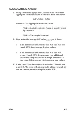
Using the following equation, calculate and record the 

aggregate correction factor for each correction sample: 

ACF =%AC

– %AC

T


where: ACF = Aggregate correction factor 

%AC

= Asphalt content of sample as determined 

by the oven 


%AC

= True asphalt content 

2.


Determine the average ACF value 

(

ACFAVG

)

 as follows: 


If the difference between the two ACF values is less 

than 0.15%, then average the two values.


If the difference between the two ACF values is 

greater than 0.15%, then prepare two additional 

correction samples. Discard the high and low ACF 

values, and then average the two remaining values.


3.


Enter the ACF as described in the 

Create ACF 

section on 

page 6-9. The oven will automatically adjust the asphalt 

content measurements using the active ACF. 

Summary of Contents for ICO 4740

Page 1: ...ction Troxler ICO NCAT Oven Model 4740 Troxler Electronic Laboratories Inc 3008 Cornwallis Rd P O Box 12057 Research Triangle Park NC 27709 Phone 1 877 TROXLER Outside the USA 1 919 549 8661 Fax 1 919...

Page 2: ......

Page 3: ...be reproduced or transmitted in any form or by any means electronic or mechanical including photocopying recording or information storage and retrieval systems for any purpose without the express wri...

Page 4: ...Grove IL 60515 Phone 1 630 261 9304 Fax 1 630 261 9341 TroxTechSupport troxlerlabs com Western Office Service Center 11300 Sanders Drive Suite 7 Rancho Cordova CA 95742 Phone 1 916 631 0234 Fax 1 916...

Page 5: ...nspection Chapter 2 Product Safety Information Includes information on the safe use of the oven Chapter 3 Installation Contains instructions for installing the oven including the criteria for selectin...

Page 6: ...service information as well as instructions on basic troubleshooting Appendix B Menu Map Shows a map of the menus in the oven control software Appendix C Specifications Contains the environmental per...

Page 7: ...n Neither the manufacturer its subsidiary distributors nor representatives can assume responsibility for any mishaps damage or personal injury that may occur from failure to observe the safety warning...

Page 8: ...that if not followed correctly may cause equipment damage NOTE Notes indicate important information that must be read to ensure proper operation KEY This style indicates a key or character to press o...

Page 9: ...WARNINGS 2 4 SAFETY WARNINGS 2 6 CHAPTER 3 INSTALLATION 3 1 SITE SELECTION 3 2 EXHAUST SYSTEM INSTALLATION 3 5 INSTALLATION WITH AN EXHAUST HOOD 3 12 INSTALLATION WITHOUT AN EXHAUST HOOD 3 15 AIRFLOW...

Page 10: ...7 MISCELLANEOUS MENU 5 31 CHAPTER 6 CALIBRATION 6 1 CORRECTING AC MEASUREMENTS 6 2 CORRECTION MENU 6 8 SCALE MENU 6 12 CHAPTER 7 HANDLING DATA 7 1 PROJECTS 7 2 PROJECT MENU 7 3 APPENDIX A MAINTENANCE...

Page 11: ...ICO ix APPENDIX C SPECIFICATIONS C 1 ENVIRONMENTAL CONDITIONS C 2 PERFORMANCE SPECIFICATIONS C 3 ELECTRICAL SPECIFICATIONS C 4 MECHANICAL SPECIFICATIONS C 5 INDEX WARRANTY...

Page 12: ...Exhaust Pipe Below the Hood Intake Edge 3 12 Figure 9 ICO Exhaust Pipe Extended into the Hood 3 13 Figure 10 External Duct Cover Open Design 3 17 Figure 11 External Duct Cover Closed Design 3 17 Figu...

Page 13: ...ICO xi Figure 21 Disengage Paper Spindle A 10 Figure 22 Insert New Paper Roll A 11...

Page 14: ......

Page 15: ...r 1 INTRODUCTION TO THE ICO This chapter provides a brief overview of the ICO This information includes a list of the parts and accessories as well as instructions for unpacking and inspecting the ove...

Page 16: ...ining clean aggregate provides the gradation The ignition oven test method is covered by the provisions of ASTM D6307 Standard Test Method for Asphalt Content of Asphalt Mixture by Ignition Method and...

Page 17: ...esses that the user is solely responsible for ensuring the safe use of the oven Neither the manufacturer its subsidiary distributors nor representatives can assume responsibility for any mishaps damag...

Page 18: ...until five minutes have elapsed since the chamber temperature has peaked or since the ABORT key was pressed Sample Basket The sample basket assembly provides operator safety while handling HMA samples...

Page 19: ...onse to a valid keystroke on the oven keypad It sounds a longer beep when the operator presses an invalid key or the oven displays an error message The annunciator sounds when the door is unlocked at...

Page 20: ...imit specified by the operator The cutoff limit can be defined in grams or as a percentage The oven can store data for up to 200 HMA samples Sample data is stored in project files created by the opera...

Page 21: ...assembly in and out of the oven 7 The sample safety cage not shown shields the hot sample basket assembly while the asphalt sample cools 8 The soft bristled brush not shown is used to brush soot from...

Page 22: ...1 8 Figure 1 Parts and Accessories...

Page 23: ...tive immediately 2 Cut the bands from around the carton then lift off the top half of the box and remove all accessory items 3 Remove any packing material packed around the oven or inside the oven cha...

Page 24: ...Troxler ICO NCAT Oven Model 4740 Manual of Operation and Instruction Universal Serial Bus USB flash drive Material Safety Data Sheet MSDS Information Kit 6 Inspect the outside surfaces of the oven and...

Page 25: ...ICO 2 1 Chapter 2 PRODUCT SAFETY INFORMATION This chapter provides basic product safety information concerning the ICO as well as cautions and warnings related to the safe use of the oven...

Page 26: ...rized experienced maintenance personnel They include removal of the rear or top panels for troubleshooting cleaning or making repairs During the performance of such maintenance operations observe the...

Page 27: ...rmation about the safe handling of refractory ceramic fiber products recommended protective measures and health hazard information For disposal information please refer to the MSDSs enclosed with the...

Page 28: ...inter the right interface is for factory use only UPPER RIGHT OF OVEN DOOR Surfaces of the oven are hot and may cause burns to unprotected skin Place oven on a non combustible surface and 15 cm 6 in a...

Page 29: ...earance above the oven WARNING The unit must not be operated without an exhaust system Refer to Chapter 3 for information on proper installation of the exhaust system REAR OF ELECTRONICS MODULE BATTER...

Page 30: ...the oven must comply with local building code rulings Troxler recommends the installation of a carbon monoxide detector Keep the area around the oven clear and free from all combustible materials gaso...

Page 31: ...all cords away from the top and sides of the oven Burning asphalt releases carbon monoxide Ensure that the oven is properly ventilated Locate the oven in a well ventilated room with access to a fume...

Page 32: ...tempt to dry any aggregates mixed with volatile chemicals Obtain and use appropriate safety equipment Troxler recommends wearing a face shield when handling hot substances and operating the oven not s...

Page 33: ...basket assembly with the sample safety cage while the sample cools To prevent personal injury do not touch the interior or exterior oven surfaces except door and control panel during use Depending upo...

Page 34: ...or maintenance Allow the oven to cool completely before performing service or maintenance Soot may build up in the exhaust connector and pipe Troxler recommends that the exhaust plenum box be cleaned...

Page 35: ...ICO 3 1 Chapter 3 INSTALLATION This chapter provides instructions on site selection and installation of the ICO...

Page 36: ...urce see Appendix C Ensure that the distance does not place stress on the power cord The power source must be wired by a qualified electrician Place the oven on a level sturdy fireproof surface Locate...

Page 37: ...site selection guidelines on the previous page set the oven in place 2 Using the adjustable feet level the oven from front to back and from side to side 3 Remove all packaging material from the oven c...

Page 38: ...ble earth ground connection or a hazardous condition may occur during oven operation NOTE The unit will use a 30 to 50 A plug It is shipped without a plug Troxler recommends a 50 A power supply circui...

Page 39: ...y installation is unique these instructions provide general guidelines on proper installation of the exhaust system Refer to local building codes and or a licensed heating ventilation and air conditio...

Page 40: ...3 6 Figure 3 Overall Schematic for Exterior Wall and Roof Penetrations Figure 4 Exterior Wall Penetration Using a Metal Elbow and Cap...

Page 41: ...and the length should not exceed 4 6 m 15 ft from the top of the oven to the point of exhaust 4 No component shall have a damper screen louver or other such device that may become clogged with soot o...

Page 42: ...cts should be 4 inches or greater and the length should not exceed 4 6 m 15 ft from the top of the oven to the point of exhaust 4 No component shall have a damper screen louver or other such device th...

Page 43: ...xhaust exits the cap must be at least 91 cm 36 in above the roof 4 The minimum thickness of all galvanized metal parts is 28 gauge or that which is called for in local building codes whichever is thic...

Page 44: ...d or a licensed HVAC contractor for recommended required distance 8 No component shall have a damper screen louver or other such device that may become clogged with soot over time 9 Refer to local bui...

Page 45: ...18 in away from the intake to the fan or blower 12 The overall diameter of all ducts should be 4 inches or greater and the length should not exceed 4 6 m 15 ft from the top of the oven to the point o...

Page 46: ...e edge must be sufficient to prevent smoke from escaping Figure 8 ICO Exhaust Pipe Below the Hood Intake Edge The air velocity at the hood intake edge is a function of the hood exhaust fan capacity an...

Page 47: ...if the hood exhaust fan capacity is insufficient to draw all the smoke out of the hood If you move the exhaust pipe close to or inside the hood exhaust duct you must ensure that there is minimal draw...

Page 48: ...he airflow lift see page 3 19 3 Turn on the hood exhaust fan 4 Measure the unit s airflow lift with both its fan and the hood exhaust fan running If the airflow lift value does not change the position...

Page 49: ...pe causing the unit warm up time and the recovery time after opening the door to increase If the airflow is excessive the unit may not heat up to the proper temperature i e 540 C 5 C at all Negative A...

Page 50: ...gate correction factors NOTE If you have trouble getting satisfactory airflow lift values contact 1 877 TROXLER 1 877 876 9537 EXHAUST PIPE LENGTH The length of the exhaust pipe must be less than fift...

Page 51: ...that incorporates louvers will create back pressure on the exhaust line see the figure below Figure 11 External Duct Cover Closed Design NOTE If a screen is added to keep out birds etc it needs to be...

Page 52: ...he unit was configured at the factory and requires very little setup before the first burn Air enters the chamber through the hole in the bottom of the furnace where the loadcell scale supports are po...

Page 53: ...ld not need adjustment Figure 13 Exhaust Plenum Box and Louvers MEASURING THE AIRFLOW LIFT NOTE Airflow lift is measured using the exhaust pipe connected to the furnace Be sure this pipe is connected...

Page 54: ...minute and monitor the mass on the control panel display If the scale drifts to any point less than or greater than 0 0 go back to step 2 Otherwise go to step 6 6 When the unit is stable close the do...

Page 55: ...NOTE If the scale does not return to 0 0 grams after repeated tries recalibrate it If this does not resolve the issue contact 1 877 TROXLER 1 877 876 9537 11 Adjust the louvers as applicable based on...

Page 56: ...om any furnace contains many noxious gases that are unsafe to breathe over an extended period When the unit is set up properly there should not be any exhaust smell in its vicinity Check frequently to...

Page 57: ...It describes the oven keypad and provides procedures for starting up the oven and setting it up for the first time daily startup and operation and shutting the oven down The procedures in this chapte...

Page 58: ...reen see page 4 5 is MENU Accesses the MAIN MENU Available only when the default screen see page 4 5 is displayed The functions available from the MAIN MENU are described in Chapters 5 7 A menu map is...

Page 59: ...e Available when the default screen is displayed STORE Manually stores data Available when the default screen is displayed following a burn cycle If no burn data is available for storage an error mess...

Page 60: ...of the oven printer Figure 15 Printer Front Panel The paper feed button activates the paper feed mechanism Paper continues to feed until the button is released For information on replacing the printer...

Page 61: ...ker power switch found in the lower left of the oven rear panel see Figure 1 1 to the ON up position This breaker does not need to be turned off during normal operation Press the on off rocker switch...

Page 62: ...ion refer to page 5 31 a The oven is shipped with the current date and time Eastern Standard Time stored in its memory By default the oven displays the date in mm dd yyyy format where mm month dd day...

Page 63: ...the burn mode to Program Time or Auto Control as desired the default setting is Auto Control Set the desired burn time and or cutoff limit Set the calculation type to bitumen to sample or bitumen to a...

Page 64: ...start and stop times and dates entered by the operator For more information refer to page 5 16 9 Determine the aggregate correction factors ACFs if necessary From the MAIN MENU press 4 to access the C...

Page 65: ...es by Washing ASTM C 136 AASHTO T27 Sieve Analysis of Fine and Coarse Aggregates ASTM D 979 AASHTO T168 Sampling Bituminous Pavement Mixtures 1 Power the oven on as follows If the Auto Timer is not en...

Page 66: ...Mode Auto Store function Auto Print function 3 The oven stores sample data in projects To manage the oven s project files press MENU to access the MAIN MENU and then press 3 to access the Project Men...

Page 67: ...et 7 Place the basket cover over the top sample basket as shown in Figure 16 Secure the sample baskets and cover to the catch pan with the lock arms Ensure that the lock arms fully engage the slots in...

Page 68: ...asket carrier to move hot sample baskets see Figure 2 on page 2 9 Always keep the basket carrier to the left side of your body with the handle between your body and the open oven door This helps preve...

Page 69: ...f the weight recorded in step 9 If it is not ensure that the hearth plate and sample baskets do not touch the chamber sides If the displayed weight is within 5 g of the weight recorded in step 9 press...

Page 70: ...he chamber door light the BURN COMPLETE indicator or sound the annunciator until five minutes have passed since the chamber temperature has peaked Typically this five minute period will have elapsed b...

Page 71: ...he Store Function section on page 5 27 for more information NOTE A project must be active in order to store For more information on using projects refer to Chapter 7 If the Auto Store option is enable...

Page 72: ...ve the on off rocker switch on the right hand side of the front panel to the on position 1 for on 0 for off The oven will automatically power down the heating element and exhaust fan at the designated...

Page 73: ...ICO 5 1 Chapter 5 MAIN MENU The operator controls and configures the ICO from the MAIN MENU its submenus and displays This chapter describes the many menu options...

Page 74: ...or greater flexibility of operation To access these options press MENU The oven displays the MAIN MENU shown below To select an item from the menu press the corresponding numeric key Use the up and do...

Page 75: ...f these menus is provided in Appendix B of this manual The remainder of this chapter describes each menu option except for the Project option which is described in Chapter 7 and the Corr Factors and S...

Page 76: ...rn time is set manually In Auto Control mode the oven automatically completes a burn cycle when the incremental mass decrease of the sample falls below a cutoff limit specified by the operator The bur...

Page 77: ...one position press the BACK SPACE key When finished press ENTER For more information on setting the burn time refer to the Burn Time section on the following page To select the Auto Control mode pres...

Page 78: ...numeric keys to set the burn time To move the cursor back one position press the BACK SPACE key When finished press ENTER The oven sets the new burn time displays a brief confirmation message and ret...

Page 79: ...change the cutoff limit press YES The oven displays Enter Cutoff Limit from 0 1 1 0g in 0 1g steps then press ENTER Use the numeric and decimal keys to enter a cutoff limit from 0 1 to 1 0 gram in in...

Page 80: ...R The oven returns to the Burn Parameter Menu Calculation Type The oven provides two methods for calculating Loss the bitumen to sample method and the bitumen to aggregate method Both methods measure...

Page 81: ...the Burn Parameter Menu Set Chamber Temp The Set Chamber Temp option allows the user to select the operating temperature of the Chamber Temperatures that are allowed are 200C to 600C To use the Set C...

Page 82: ...he screen below momentarily displays before returning to the Burn Setup Menu Chamber Temp set to xxxxC AUTO PRINT The Auto Print function automatically prints sample data during a burn cycle The oven...

Page 83: ...put in REDUCED format To enable a reduced printout press YES to enable a standard printout press NO The oven updates the Auto Print status displays a brief confirmation message and returns to the Burn...

Page 84: ...stores sample data upon completion of a burn cycle The data is stored under the active project using a sequential auto sample ID number When a new project is created the sample ID number for the Auto...

Page 85: ...then turned off and the operator manually stores data from two more burn cycles using sample IDs 3 and 4 If the Auto Store function is then turned on the sample data for successive burn cycles will al...

Page 86: ...age is now ON Project XXXXXXXXXXXX Next Sample XX No Project Data If the operator attempts to turn the Auto Store function on but no projects have been created the oven displays No Project Data do you...

Page 87: ...ed in Chapter 7 After the project is selected the oven sets the project as active briefly displays the confirmation shown on page 5 28 and then returns to the Burn Setup Menu To create a new project I...

Page 88: ...oven on or off To re enable the Auto Timer the operator must re enter all of the Auto Timer parameters start and stop dates and times and so on If the Auto Timer is suspended the oven retains all of t...

Page 89: ...ow The stop date is the date after which the Auto Timer will not power up the heating element mm dd yyyy Input Stop Date then press ENTER The top line of the display shows the current setting for the...

Page 90: ...ed To ensure consistent repeatable results If the start time is valid the oven requests the stop time for the Auto Timer as shown below The stop time is the time of day when the Auto Timer is to turn...

Page 91: ...er is active do you want to disable it To return to the MAIN MENU without disabling the Auto Timer press NO To disable the Auto Timer press YES The oven displays the message Auto Timer is Disabled and...

Page 92: ...and returns to the MAIN MENU To re enable the Auto Timer after it has been suspended press 2 at the MAIN MENU shown on page 5 2 The oven displays Auto Timer Suspended 1 Re enable 2 Disable To re enab...

Page 93: ...files The Project Menu enables the operator to create a new project to select the active project from a list of created ones and to view erase print or download project data The functions available fr...

Page 94: ...MENU The oven stores up to twenty operator defined aggregate correction factors ACFs The Correction Menu enables the operator to create select and erase ACFs The Correction Menu is described in Chapte...

Page 95: ...ale that continuously monitors the sample mass loss during a burn cycle The Scale Menu enables the operator to tare the scale either manually or automatically and to verify and calibrate the scale The...

Page 96: ...to scroll through the menu options Status Menu 1 View 2 Print 3 Download Status Menu 4 Auto Status Print VIEW STATUS To view the system status information press 1 The oven displays five screens showi...

Page 97: ...Status Menu While printing the oven displays Printing data please wait When finished the oven returns to the Status Menu DOWNLOAD STATUS To download the system status information from the oven connec...

Page 98: ...tatus Print menu as shown below Auto Status Print 1 On 2 Off To return to the Status Menu without changing the Auto Status Print function press ESC To turn the Auto Status Print function on press 1 Th...

Page 99: ...the oven displays an error message and returns to the previous display NOTE The Auto Store sample ID number is not incremented if sample data is stored manually When using the manual Store function th...

Page 100: ...hen press ENTER Enter a sample number up to six numerals Troxler recommends that manually stored samples be numbered beginning at 100 or higher When the sample number is complete press ENTER If there...

Page 101: ...sage and then requests the sample number as described in the Active Project Selected section on page 5 28 NO PROJECT SELECTED If the operator initiates the Store function and there is sample data to b...

Page 102: ...5 30 and then requests the sample number as described in the Active Project Selected section on page 5 28...

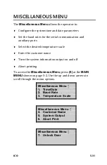
Page 103: ...ed temperature scale Enter the customer name Turn the system information output on and off Abort printing To access the Miscellaneous Menu press 8 at the MAIN MENU shown on page 5 2 Use the up and dow...

Page 104: ...me Format Time Date Menu 4 Date Format Set Time To set the current time press 1 at the Time Date Menu The oven displays hh mm AM Arrows toggle AM PM Input Time and Press ENTER Note that in this exampl...

Page 105: ...displayed date press ENTER To change the date use the numeric keys to enter the new date When finished press ENTER The oven sets the date and returns to the Time Date Menu Time Format The oven can di...

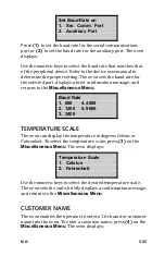
Page 106: ...he rear of the oven The serial communications port the leftmost of the two ports is used to connect the oven to an RS 232 serial device such as a printer or computer The auxiliary right port is intend...

Page 107: ...and returns to the Miscellaneous Menu Baud Rate 1 600 4 4800 2 1200 5 9600 3 2400 TEMPERATURE SCALE The oven can display the temperature in degrees Celsius or Fahrenheit To select the temperature scal...

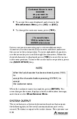
Page 108: ...the characters When the desired character is displayed press YES to move the cursor to the next position To move the cursor back one position press the BACK SPACE key NOTE After the last character ha...

Page 109: ...ly during a burn cycle Current percentage mass loss applies only during a burn cycle takes into account the current calculation typesetting Current corrected AC applies only during a burn cycle To ena...

Page 110: ...K DOOR The Unlock Door function allows the operator to unlock the chamber door if the sample burn time is less than 30 minutes or under any other condition from the default screen To unlock the door p...

Page 111: ...alibrating and verifying operating parameters for the ICO The information includes procedures for determining an aggregate correction factor ACF for using the Correction Menu to manage ACFs and for us...

Page 112: ...sphalt content measurements The magnitude of the mass loss effect is influenced most by the type of aggregate Granite aggregates have been shown to yield the least mass loss while limestone aggregates...

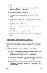
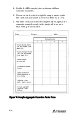
Page 113: ...in Figure 6 1 PREPARING CORRECTION SAMPLES See the safety warnings in Chapter 2 Refer to Figure 18 on the following page for a sample form for recording and calculating data To prepare correction samp...

Page 114: ...ternal scale to weigh the sample baskets with the catch pan and basket cover Record the mass WP 6 With the catch pan under the sample baskets spread the correction sample evenly in the baskets Put no...

Page 115: ...insulation of the inside surface of the door 7 Place the sample basket cover over the top sample basket 8 Use the lock arms to secure the sample basket cover to the top basket 9 Place the sample with...

Page 116: ...oven during ignition Do not override the door lock 16 After ignition is complete the oven releases the door lock and prints a summary of the sample burn data Wearing insulated gloves and a face shield...

Page 117: ...e the average ACF value ACFAVG as follows If the difference between the two ACF values is less than 0 15 then average the two values If the difference between the two ACF values is greater than 0 15 t...

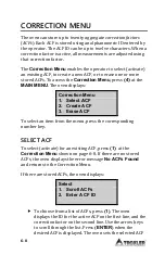
Page 118: ...isplays Correction Menu 1 Select ACF 2 Create ACF 3 Erase ACF To select an item from the menu press the corresponding number key SELECT ACF To select activate for an existing ACF press 1 at the Correc...

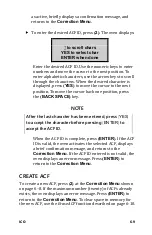
Page 119: ...K SPACE key NOTE After the last character has been entered press YES to accept the character before pressing ENTER to accept the ACF ID When the ACF ID is complete press ENTER If the ACF ID is valid t...

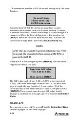
Page 120: ...character has been entered press YES to accept the character before pressing ENTER to accept the ACF ID When the ACF ID is complete press ENTER The oven then requests the new ACF value Input new ACF...

Page 121: ...CF for erasure press ENTER when the oven displays the ACF ID To select a known ACF ID to be erased press 2 The oven displays to scroll chars YES to select char ENTER when done Enter the desired ACF ID...

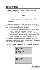
Page 122: ...with the following standards AASHTO M 231 Standard Specification for Weighing Devices Used in the Testing of Materials ASTM D 4753 Standard Specification for Evaluating Selecting and Specifying Balanc...

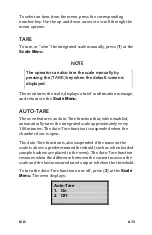
Page 123: ...AUTO TARE The oven features an Auto Tare function that when enabled automatically tares the integrated scale approximately every 100 minutes The Auto Tare function is suspended when the chamber door...

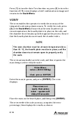
Page 124: ...ss Ensure that the hearth plate does not touch the chamber sides NOTE The oven chamber must be at room temperature less than 35 C the hearth plate must be in place and the chamber door must remain ope...

Page 125: ...do you want to calibrate To continue without calibrating the scale press NO or ESC The oven returns to the Scale Menu To calibrate the scale press YES The oven proceeds as described in the Calibrate...

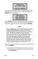
Page 126: ...librate Prompt shown on the previous page To calibrate the scale from the Scale Menu press 4 If the chamber is at the proper temperature below 35 C and the door is open the oven displays Enter number...

Page 127: ...roxler recommends using a 5000 g ANSI ASTM Class 4 or NIST Class P mass over that span the range over which the oven will be used The lowest point of this range should be slightly less than the mass o...

Page 128: ...r decreases their correlation coefficient is close to 1 If two variables have a positive linear relationship one variable increases as the other increases their value is close to 1 In an ideal scale c...

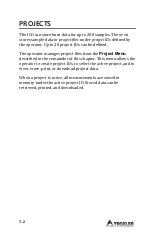
Page 129: ...NDLING DATA The ICO can store sample data for viewing and printing later This data is stored in projects This chapter explains how to use the Project Menu to create select view erase print and downloa...

Page 130: ...efined The operator manages project files from the Project Menu described in the remainder of this chapter This menu allows the operator to create project IDs to select the active project and to view...

Page 131: ...u options Use the numeric keys to select a menu option SELECT The Select function allows the operator to activate an existing project To select an existing project press 1 at the Project Menu shown ab...

Page 132: ...OTE After the last character has been entered press YES to accept the character before pressing ENTER to accept the project ID When the project ID is complete press ENTER If the project ID entered is...

Page 133: ...nfirmation message and returns to the Project Menu VIEW To view the sample data for a selected project press 3 at the Project Menu shown on page 7 3 The oven displays View 1 Scroll Projects 2 Enter Pr...

Page 134: ...NTER while the sample data is displayed When finished press ESC to return to the Project Menu ERASE The Erase function allows the operator to erase a selected project or all projects To access the Era...

Page 135: ...n erases the project displays a brief confirmation message and returns to the Project Menu To return to the Project Menu without erasing the project press NO or ESC PRINT The Print function allows the...

Page 136: ...des only a header and footer and a summary of the burn data While printing the selected project data the oven displays Printing data please wait When finished printing the oven returns to the Project...

Page 137: ...es as described in the Select section on page 7 3 to select or enter the desired project ID To output all projects press 2 The oven prompts do you want to output in REDUCED format To enable a reduced...

Page 138: ......

Page 139: ...ICO A 1 Appendix A MAINTENANCE AND SERVICE This appendix contains information on maintaining and servicing the ICO...

Page 140: ...age A 12 OVEN DOES NOT TURN ON Ensure that the oven is plugged into an outlet and that the circuit breaker for the outlet is on Check that the circuit breaker power switch at the lower left corner of...

Page 141: ...stem should be cleaned regularly The oven monitors the total burn time that has elapsed since the last cleaning Upon completion of a burn cycle if this elapsed time exceeds 1050 minutes the oven displ...

Page 142: ...e ICO to smoke if the fan is removing a high volume of air from the lab Check cooling fans hood fans etc Turn off the fan or open an exterior door to help equalize air pressure in the room with outsid...

Page 143: ...tal burn time since the last cleaning is 1050 minutes or greater the oven displays WARNING Clean ICO Exhaust System See Operation Manual for details Press ENTER When this warning is displayed Troxler...

Page 144: ...aned and the operator has pressed YES in response to the reminder WARNING To prevent personal injury or equipment damage turn the oven circuit breaker power switch off unplug the oven and allow the ov...

Page 145: ...rovided with the oven gently brush all soot from the turbine blades of the exhaust fan CAUTION Use care when cleaning the turbine to prevent bending the blades If a blade is bent the turbine will be u...

Page 146: ...the polarity of the battery when installing it in the battery holder A battery may explode or leak if installed improperly The battery holder is located on the back of the electronics module To repla...

Page 147: ...attery indication turn the circuit breaker power switch off then on again REPLACING THE PRINTER PAPER To replace the paper roll in the printer 1 As shown in the following figure open the bottom printe...

Page 148: ...t to disengage the paper spindle as shown in the following figure Figure 21 Disengage Paper Spindle 4 Insert new paper roll into the printer Make sure that the paper feeds from the top of the roll and...

Page 149: ...ert New Paper Roll 5 Press the paper feed button to ensure that the paper feeds freely REPLACING FUSES Repair or replacement of fuses should be performed only by qualified service personnel Troxler Se...

Page 150: ...used to cushion the inside of the chamber door The box folds for easy storage Please have the following information available when requesting an RGA number Unit or part model and serial number Part nu...

Page 151: ...ICO A 13 NOTE To prevent order duplication if an order has been placed by telephone please write Confirming Order on any follow up written requests...

Page 152: ......

Page 153: ...ICO B 1 Appendix B MENU MAP This appendix provides a map of the menus in the ICO control software...

Page 154: ...tup Me nu 1 B u r n P a r a m e t e r s Bur n Parame ter Menu This indicates that the first menu item under the MAIN MENU is 1 Burn Setup Press 1 to access the Burn Setup Menu a submenu of the MAIN ME...

Page 155: ...Menu 1 Burn Mode Choose Burn Mode 1 Program Time 2 Auto Control 3 Burn Time 2 Set Chamber Temp 3 Cutoff Limit Cutoff Units 1 Grams 2 Percentage 4 Calculation Type Calculation Type 1 Bitumen to Sample...

Page 156: ...un 3 Both 4 None Auto Timer Enabled 1 Suspend 2 Disable Auto Timer Suspended 1 Re enable 2 Disable 3 Project Project Menu 1 Select Select 1 Scroll Projects 2 Enter Project ID 2 Create 3 View View 1 Sc...

Page 157: ...rojects 5 Print Output 1 One Project Select 1 Scroll Projects 2 Enter Project ID 2 All Projects 6 Download 1 One Project Select 1 Scroll Projects 2 Enter Project ID 2 All Projects 4 Corr Factors Corre...

Page 158: ...Select 1 Scroll ACFs 2 Enter ACF ID 2 All ACFs 5 Scale Scale Menu 1 Tare 2 Auto Tare Auto Tare 1 On 2 Off 3 Verify 4 Calibrate 6 Status Status Menu 1 View 2 Print 3 Download 4 Auto Status Print Auto...

Page 159: ...e Time Date Menu 1 Set Time 2 Set Date 3 Time Format Time Format 1 AM PM 2 24 Hour 4 Date Format Date Format 1 mm dd yyyy 2 dd mm yyyy 2 Baud Rate Set Baud Rate on 1 Ser Comm Port Baud Rate 1 600 2 12...

Page 160: ...8 3 2400 4 4800 5 9600 3 Temperature Scale Temperature Scale 1 Celsius 2 Fahrenheit 4 Customer Name 5 System Output System Info Output 1 Always On 2 During Burn Only 3 Off 6 Abort Print 7 Unlock Door...

Page 161: ...ICO C 1 Appendix C SPECIFICATIONS This appendix contains specifications for the ICO...

Page 162: ...Storage 55 to 85 C Temperature 67 to 185 F Ambient Operating 10 to 50 C Temperature 50 to 122 F Altitude Rating 2000 m maximum Main Supply Voltage 10 Fluctuation Pollution Degree 2 Installation Categ...

Page 163: ...emperature sensors Type K thermocouples see note below NOTE The ignition method employed by the ICO does not require precise control of the chamber or other temperatures If desired oven performance ca...

Page 164: ...ter Keypad 25 key sealed membrane RS 232C configuration Data Terminal Equipment DTE Serial data format 8 data bits 2 stop bits no parity Baud rate range 600 to 9600 baud Maximum length of serial cable...

Page 165: ...L SPECIFICATIONS Outside dimensions 24 W x 32D x 33 5 H in Chamber dimensions 13 W x 20 D x 11 5 H in Weight 160 lbs Sample basket dimensions H in each 8 W x 14 5 D x 1 6 H in Basket assembly 9 4 W x...

Page 166: ......

Page 167: ...rd D 6307 1 2 D 4125 1 2 annunciator 1 5 4 14 Arrow keys 4 2 Auto Control 1 6 4 7 5 4 Auto Print4 7 5 4 5 10 6 5 Auto Status print 5 26 Auto Store1 6 4 7 4 10 5 12 Auto Tare 1 4 6 13 Auto Timer 1 5 4...

Page 168: ...or Lock 1 4 Unlock 5 38 ENTER Key 4 2 ESC Key 4 2 Exhaust Installation 3 5 Features 1 4 Fuses Replacing A 11 Inspecting 1 9 Installation 3 1 Exhaust System 3 5 Oven 3 3 Site Selection 3 2 Keypad 4 2 M...

Page 169: ...Menu 5 23 Tare 6 13 Verify 6 14 Self test 4 5 Service Centers ii Set Chamber Temperature 5 9 Site selection 3 2 Specifications C 1 Electrical C 4 Environmental Conditions C 2 Mechanical C 5 Performan...

Page 170: ......
Page 171: ...ANTY IS EXPRESSLY IN LIEU OF ALL OTHER WARRANTIES EXPRESSED OR IMPLIED AND TROXLER NEITHER ASSUMES NOR AUTHORIZES ANYONE TO ASSUME FOR IT ANY OTHER LIABILITY IN CONNECTION WITH THE SALE OF THE INSTRUM...

Reviews: