background image

32

MODEL 675B

Transmission

(618-04002)

Summary of Contents for 675B Pony

Page 1: ...eeting applicable local or state laws if any If a spark arrester is used it should be maintained in effective working order by the operator In the State of California the above is required by law Section 4442 of the California Public Resources Code Other states may have similar laws Federal laws apply on federal lands A spark arrester for the muffler is available through your nearest engine author...

Page 2: ... unit you can seek help from the experts Choose from the options below Visit troy bilt com for many useful suggestions Click on Customer Support button and you will get the four options reproduced here Click on the appropriate button and help is immediately available If you prefer to reach a Customer Support Representative please call 1 800 520 5520 The engine manufacturer is responsible for all e...

Page 3: ...rettes cigars pipes open flames and sparks away from the fuel tank and fuel container d Fill fuel tank outdoors with extreme care Never fill fuel tank indoors Use a funnel or spout to prevent spillage e Replace all fuel tank and container caps securely f If fuel is spilled do not attempt to start the engine but move the machine away from the area of spillage and avoid creating any source of igniti...

Page 4: ...o not overload the tiller s capacity by attempting to till too deeply at too fast a rate 16 Never operate the tiller at high trans port speeds on slippery surfaces Look be hind and use care when backing up 17 Do not operate the tiller on a slope that is too steep for safety When on slopes slow down and make sure you have good footing Never permit the tiller to freewheel down slopes 18 Never allow ...

Page 5: ...ages on tine hood Hot Surfaces Moving Belts Warning on belt cover Operating Symbols Varioussymbols shownhere withworddescriptions maybeusedonthetillerandengine NOTE Yourunitmaynothaveallofthesymbols FAST SLOW STOP TILLER DIRECTION LEVER DIRECTION ROTATING TINES REVERSE R CHOKE OFF CHOKE ON WARNING TO AVOID SERIOUS INJURY READ THE OPERATOR S MANUAL KNOW LOCATIONS AND FUNCTIONS OF ALL CONTROLS KEEP ...

Page 6: ...ee Figure 2 2 5 2 3 8 Flat Washer 6 2 10 Lock washer 7 2 3 8 16 Nylock Lock Nut 8 2 10 32 x 1 2 Rnd Hd Screw 9 2 10 32 Nut 10 1 Cotter Pin not used 11 4 Plastic Tie Strap 2 not used Tools Materials Needed for Assembly 1 3 8 open end wrench 2 9 16 open end wrench 1 7 8 open end wrench 1 Scissors to trim plastic ties 1 Ruler 1 Small board to tap plastic knob on lever 1 Tire pressure gauge 1 Clean oi...

Page 7: ...installed on the ca ble 2 Insert the cable into the slot in the con trol panel and fit the threaded assembly into the hole in the slot see Figure 2 6 Be sure that the flat side of the threaded as sembly is aligned with the flat side of the hole Slide the hex nut I up the cable and tighten it securely 3 Test the function of the reverse clutch control cable by pulling the knob out and releasing it T...

Page 8: ...around the fill hole N Fig ure 2 11 and unscrew gear oil fill plug b If adding only a few ounces of gear oil use API rated GL 4 or GL 5 gear oil having a viscosity of SAE 140 SAE 85W 140 or SAE 80W 90 If refilling an empty trans mission use only GL 4 gear oil having a viscosity of SAE 85W 140 or SAE 140 c Using a clean funnel slowly add gear oil until it flows from the gear oil level check hole N ...

Page 9: ...ss Wheel Gear Lever is in ENGAGE Engaging the Forward Clutch or Reverse Clutch when wheels are not engaged could allow the tines to rapidly propel tiller backward Failure to follow this warning could result in personal injury or property damage To Operate Forward Clutch 1 Before engaging the Forward Clutch put the Wheel Gear Lever into the ENGAGE position see WARNING above 2 Lift and hold one or b...

Page 10: ... mind that the handlebars will be lower when the tines are engaged in the soil WARNING Whenever the handlebar height is changed the Forward Clutch shift mechanism must be readjusted Before adjusting or checking the Forward Clutch mechanism shut engine off disconnect spark plug wire and prevent it from touching spark plug Failure to follow this warning could cause the Forward Clutch mechanism to op...

Page 11: ... 3 Check that all safety guards and covers are in place 4 Check air cleaner and engine cooling system See Engine Owner s Manual 5 Select a forward belt speed range see Changing Belt Speed Ranges in this Sec tion 6 Fill the fuel tank with gasoline according to the directions in the separate Engine Owner s Manual Follow all instructions and safety rules carefully DANGER GASOLINE IS HIGHLY FLAMMABLE ...

Page 12: ...ward Clutch levers against the handlebars To stop the wheels and tines release both le vers WARNING Do not push down on the handlebars to try to make the tiller till more deeply This prevents the wheels from holding the tiller back and can allow the tines to rapidly propel the tiller backward toward the operator which could result in loss of control property damage or personal injury b As the till...

Page 13: ...e is pulled 6 Check that the belt is within the forward belt guide E Figures 4 10 and 4 11 on the right side of the unit and is within the for ward idler F Figure 4 11 on the left side Be sure that the belt is situated in the center grooves C and D Figure 4 10 of the en gine upper and transmission lower pul leys 7 Reinstall the plastic belt cover and se cure it with the two nuts 8 Put Wheel Gear L...

Page 14: ...hrottle lever at a speed to give the engine adequate power and yet allow it to operate at the slowest possible speed at least until you have achieved the maximum tilling depth you desire Faster engine speeds may be desirable when making final passes through the seedbed or when cultivating Selection of the correct engine speed in relation to the tilling depth will ensure a sufficient power level to...

Page 15: ... debris It may be necessary to remove the debris by hand a pocket knife will help you to cut away the material Be sure to stop the engine and disconnect the spark plug wire before clearing the tines by hand WARNING Before clearing the tines by hand stop the engine allow all moving parts to stop and disconnect the spark plug wire Remove the ignition key on electric start models Failure to follow th...

Page 16: ... Oil the outer casings of the engine throt tle cable and the wheel gear cable E Figure 5 1 Allow oil to soak in and then wipe off any excess Oil the various pivot points F Figure 5 2 on the shifting mechanism the han dlebar and the idler arms do not allow oil on the belts or pulleys Check Tire Air Pressure Check the air pressure in both tires Deflate or inflate both tires evenly to between 15 and ...

Page 17: ... to a level area and stop the engine 2 Level the engine by moving the Depth Regulator Lever into the second notch from the top 3 Clean the area around the oil dipstick or oil fill tube whichever applies to prevent dirt from falling into the crankcase 4 On engines with an oil fill tube remove the filler cap and add oil if required until it reaches the top of the tube Reinstall the filler cap 5 On e...

Page 18: ...e engine storage instructions in the separate Engine Owner s Manual NOTE Be sure to protect the fuel lines car buretor and fuel tank from gum deposits by removing fuel or by treating fuel with a fuel stabilizer follow engine manufactur er s recommendations 4 Store unit in a clean dry area 5 Never store the tiller with fuel in the fuel tank in an enclosed area where gas fumes could reach an open fl...

Page 19: ...d Adjust Tension on the Forward Drive Belt 1 Checking for correct belt tension is the same as that described in item 5 Step 4 Attach Forward Clutch Rod Before check ing shut off the engine disconnect the spark plug wire and allow the engine and muffler to cool down If after following the adjustment procedures you cannot get the correct gap on the forward clutch rod adjustment bracket you will need...

Page 20: ...the belt cover after first shut ting off the engine disconnecting the spark plug wire and allowing the engine and muffler to cool down 2 Stand at the front of the tiller and use your left hand to push the reverse idler arm K Figure 5 13 inward as far as pos sible the reverse idler pulley L is at tached to the reverse idler arm Hold the idler arm in this position and look at the position of the bel...

Page 21: ...nd one reverse speed The for ward engine pulley D Figure 5 16 has two grooves for the two forward speeds The reverse engine pulley A Figure 5 16 has one groove for the one reverse speed The transmission pulley C Figure 5 16 has three grooves The groove closest to the engine is for the reverse belt The mid dle groove is for the High speed forward belt range the rearmost groove is for the Low speed ...

Page 22: ...ated below the trans mission pulley 3 Slip the reverse belt off the engine re verse pulley A Figure 5 18 If necessary work the belt off the pulley with your left hand while pulling the engine recoil starter rope with your right hand 4 Push the upper half of the reverse belt downward to create slack in the belt Then reach underneath the transmission and slip the belt off the front of the transmis s...

Page 23: ... Owner s Manual Engine overheats 1 Engine cooling system clogged 1 Clean air cooling area see Engine Owner s Manual 2 Carburetor out of adjustment 2 See Engine Service Dealer 3 Oil level is low 3 Check oil level see Engine Owner s Manual Engine does not shut off 1 Misadjusted throttle control or ignition switch 1 See Engine Owner s Manual or Engine Service Dealer Wheels and Tines will not turn 1 I...

Page 24: ...24 HANDLEBAR ASSEMBLY and CONTROL LEVERS 10 SECTION 6 PARTS LIST ...

Page 25: ...6 x 1 8 736 3050 Washer Plain flat 3 8 S A E 9 712 3000 Hex Locknut 3 8 16 10 746 04027 Forward Clutch Control Cable 13 1916639 Wheel Clutch Control 14 GW 9057 Knob Wheel Gear Control Lever 15 1186211 Hex Nut 5 16 24 16 GW 90064 Hex Hd Screw 3 8 16 x 3 4 17 736 0169 Lock washer 3 8 19 725 0157 Cable Ties Plastic 21 1114748 Round Hd Screw 10 32 x 1 2 22 1100240 Lock washer 10 23 1186208 Hex Nut 10 ...

Page 26: ... Cable Screw Ref 47 secures Forward Clutch Cable page 25 Ref 10 5 6 7 7 3 4 13 14 15 16 17 16 52 21 18 20 3 44 38 47 53 54 41 37 44 3 51 25 24 23 8 29 28 19 27 26 30 22 11 12 50 49 46 39 45 20 45 1 40 42 48 12 11 8 9 10 2 35 36 31 ...

Page 27: ...asher Flat 1 1 8 21 1916728 Spring Reverse Return 22 1916522 Transmission Pulley 23 GW 1440 Support Washer 24 1918812 Reverse Clutch Belt 25 1909404 Forward Clutch Belt 26 1900396 Self tapping Screw 10 32 x 1 2 27 GW 20339 Guard Belts Pulleys 28 712 04063 Flange Lock Nut 5 16 18 29 1186329 Hex Flange Screw 5 16 18 x 3 4 30 1916797 Engine Support Bracket left side 31 1916796 Engine Support Bracket ...

Page 28: ...er Incl four Ref 18 7 GW 20694 Gasket Transmission Top Cover 8 619 04010 Transmission Case Assy 9 GW 9467 Plug 10 1917101 Mounting Plate Wheel Clutch Cable 11 721 04035 Oil Seal Tiller Shaft 12 710 04049 Hex Flange Screw 5 16 18 x 5 8 13 GW 20873 Tiller Housing Cover left side 14 GW 1129 1 Gasket Tiller Housing Cover 010 A R 15 1915069 Self Sealing Screws 1 4 20 x 7 8 16 GW 1115 Rear Bearing Cap 1...

Page 29: ...Cap 010 thick see Note below A R 5 GW 1224 2 Shim same as above but 030 thick see Note A R 5 GW 1224 3 Shim same as above but 005 thick see Note A R 5 GW 1224 4 Shim same as above but 062 thick see Note A R GW 1325C Shim Set Incl two GW 1224 1 two 1224 2 and one GW 1224 3 A R 6 GW 9572 Hex Hd Screw 5 16 24 x 1 1 8 1 7 GW 9944 Washer Disc Spring concave surface faces pulley 8 1108841 Key 3 16 sq x ...

Page 30: ...86 Bushing 5 711 04091 Wheel Shaft Incl Ref 6 6 GW 9373 Hi Pro Key 1 4 x 1 5 16 7 GW 20914 Wheel Drive Worm Gear cast iron 8 GW 9935 Shim 6 I D x 1 468 O D x 062 9 GW 20712 Wheel Drive Clutch cast iron 10 611 04002 Eccentric Shaft 11 GW 1442 Pin Eccentric Shaft 12 GW 9055 Spring 13 721 04034 Oil Seal 14 786 04001 Eccentric Shaft Lever 15 710 3013 Hex Hd Screw 1 4 20 x 1 2 16 741 3037 Ball Bearing ...

Page 31: ...96 Hex Hd Screw 3 8 16 x 2 Grade 8 6 GW 9338 Hitch Pin 7 1985100 Tine left hand 8 GW 9380 Clevis Pin 312 x 1 3 4 long 9 634 04033 Wheel Tire Assy left side 10 634 04032 Wheel Tire Assy right side REF NO PART NO DESCRIPTION Mount Tines So The Cutting Edge At The Top Of Each Tine Faces The Operator IMPORTANT LEFT and RIGHT sides of tiller are determined by standing in the operator position BEHIND TH...

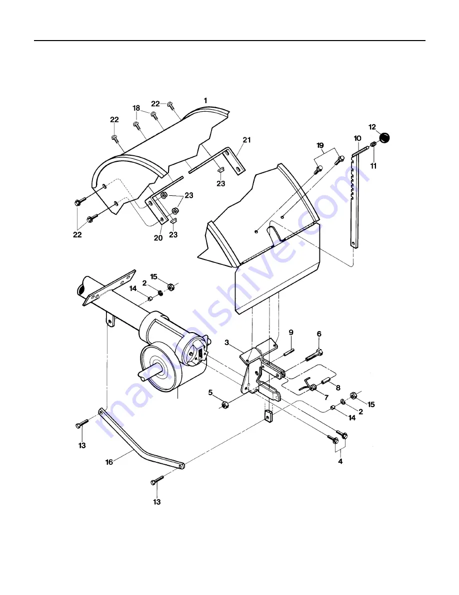
Page 32: ...32 MODEL 675B Transmission 618 04002 ...

Page 33: ...Assembly Depth Adjustment 11 GW 9120 Retaining Ring Tolerance Ring 12 GW 9119 Knob Depth Regulator Incl Ref 11 13 710 3005 Hex Hd Screw 3 8 16 x 1 1 4 14 GW 1113 1 Bushing spacer 15 712 3017 Hex Nut 3 8 16 16 GW 20775 Drag Bar Depth Regulator 18 710 0759 Hex Hd Screw self tapping 16 18 x 1 2 19 710 0599 Flange Screw self tapping 1 4 20 x 1 2 20 1916700 Support Bracket Left Side 21 1916701 Support ...

Page 34: ...DEL 675B BUMPER OEM 290 254 BUMPER ATTACHMENT 19 20 23 22 21 ROW MARKER ATTACHMENT OPTIONAL 8 8 9 9 2 6 6 7 3 5 10 11 12 14 14 16 17 18 13 15 ROW MARKER ATTACHMENT OEM 290 257 ATTACHES TO FURROWER ATTACHMENT ...

Page 35: ...1100135 screws 10 1186349 Screw hex flanged locking 3 8 16 x 1 1 2 11 GW 1593 Stop Bar 12 GW 1592 Yoke 13 GW 1591 Tube Key square 14 GW 1590 Washer friction 15 GW 1588 Main Support 16 GW 1589 Washer square hole 17 GW 9925 Washer disc spring 18 712 0798 Nut hex 3 8 16 19 749 04193 Bumper 20 777S30653 Decal Caution 21 710 3073 Screw hex hd 5 16 18 x 2 1 4 22 726 0201 Speed Nut 23 712 04063 Nut Flang...

Page 36: ... commercial institutional industrial rental or demonstrator purposes the warranty COMMERCIAL on the tiller is limited in duration to 90 days from the date of purchase USE WARRANTY This warranty does not apply to parts that have been damaged by accident alteration misuse abuse neglect improper maintenance vandalism theft fire water or damage because of peril or other natural disaster HOW TO OBTAIN ...

Reviews: