background image

Summary of Contents for SpringAssist TB25ET

Page 1: ...v Gasoline Trimmer Edger el TB25ET iMPORTANT READ SAFETY RULES AND iNSTRUCTiONS CAREFULLY PiN 769 01344 10 04 PRINTED IN USA...

Page 2: ...ation 2 Rules for Safe Operation 3 Know Your Unit 6 Assembly Instructions 7 Oil and Fuel Information 8 Starting Stopping Instructions 9 Operating Instructions 10 Maintenance and Repair Instructions 13...

Page 3: ...hildren and teens under the age of 15 must not use the unit except for teens guided by an adult Aii guards and safety attachments must be installed properly before operating the unit Inspect the unit...

Page 4: ...king from one cutting location to another Stop and switch the engine to off for maintenance repair or for changing the cutting attachment or other attachments If you strike or become entangled with a...

Page 5: ...oud noise can cause severe eye injury and hearing loss Wear eye protection meeting ANSI Z87 1 1989 standards and ear protection when operating this unit Use a full face shield when needed I O iViEAN_N...

Page 6: ...used with the TB25ET Refer to Operating the EZ Link System for a Hist of add ons Air Filter Muffler Cover Shaft Grip Throttle Control Shoulder Strap Clip _ Starter Rope Grip Throttle Lock Out J Handm...

Page 7: ...uches the clamp assembly Fig 2 You must first loosen the screws if the handle is pre installed F_g 2 6 While holding the unit in the operating position Fig 3 position the J handle to the location that...

Page 8: ...with a fuel additive such as STA B L Gas Stabilizer or an equivalent Add 0 8 oz 23 ml of fuel additive per gallon of fuel according to the instructions on the container NEVER add fuel additives direct...

Page 9: ...Repeat until the engine starts NOTE The unit uses Spring Assist Starting TM which significantly reduces the effort required to start the engine You must pull the starter rope out far enough to hear th...

Page 10: ...10 installing the Cutting Attachment or Add Ons NOTE To make installing or removing the add on easier place the unit on the ground or on a work bench 1 Turn knob counterclockwise to loosen Fig 9 EZoL...

Page 11: ...becomes more difficult when the cutting line gets shorter NOTE Do not rest the Bump Head TM on the ground while the unit is running Some line breakage wi occur from Entanglement with foreign matter N...

Page 12: ...ightHy bentright arm the operator s hand is hoHding the shaft grip The operator s left arm is straight the left hand holding the J handle The unit is at waist eve The edger wheel is adjusted for prope...

Page 13: ...ay result from contaminants involved in the cleaning process for the port FREQUENCY MAINTENANCE REQUIRED REFER TO Before starting engine Fill fuel tank with fresh fuel Page 8 Every 10 hours Clean and...

Page 14: ...is inserted correctly 7 Repeat procedures 4 6 with the second piece of line 8 Hold the outer spook Wind the inner reel counterclockwise until approximately four 4 inches 102 mm of line remain Fig 22 N...

Page 15: ...es not operate correctly when bumping the head on the ground 1 Hold the outer spool and unscrew the bump knob counterclockwise Fig 26 2 Pull out the bump knob spring and foam sea Fig 24 4_ Remove any...

Page 16: ...put shaft hole Make sure that the blade stays flat and centered against the output shaft while tightening the lock nut counterclockwise Fig 33 If you have a torque wrench tighten the nut to 325 335 in...

Page 17: ...fler cover Refer to Removing the Air Filter Muffler Cover 2 Turn cover over and look inside to locate the air filter Remove the air filter from inside the air filter muffler cover Fig 35 3 Wash the fi...

Page 18: ...arrestor screen with a wire brush Replace it if it is damaged or if you are unable to clean it thoroughly 5 Reinstall the spark arrestor screen by putting the raised portion of the screen inside the r...

Page 19: ...warm up Refer to Starting Stopping Instructions WARNmNG The cutting attachment may spin during idle speed adjustments Wear protective clothing and observe all safety instructions to prevent serious p...

Page 20: ...soft cloth STORAGE Never store the unit with fuel in the tank where fumes may reach an open flame or spark Allow the engine to cool before storing Store the unit locked up to prevent unauthorized use...

Page 21: ...theair filter Drain gas tank and add fresh fuel mixture Adjust according to the Carburetor Adjustments section ACTION Drain gas tank and add fresh fuel mixture Take to an authorized service dealer for...

Page 22: ...Steel Tube EZ Link TM Throttle Control Finger Tip Trigger with Lock out Approximate Unit Weight No fuel with cutting attachment shield and J handle 12 25 Ibs 5 6 kg Cutting Mechanism SpeedSpooP Dual S...

Page 23: ...0 Manufacturer s Warranty Coverage The warranty period begins on the date the engine or equipment is delivered to the retail purchaser The manufacturer warrants to the initial owner and each subsequen...

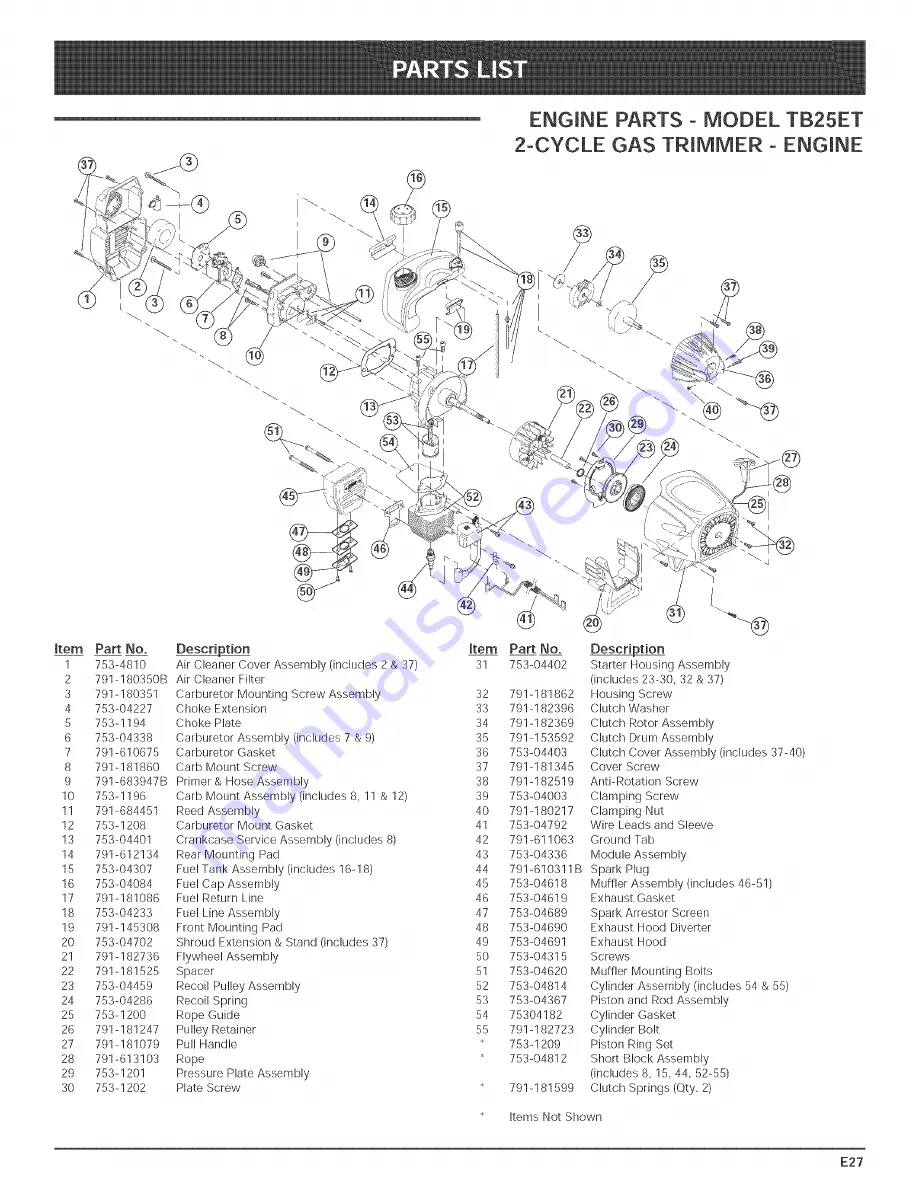
Page 24: ...23 753 04459 Recoil Pulley Assembly 52 24 753 04286 Recoil Spring 53 25 753 1200 Rope Guide 54 26 791 181247 Pulley Retainer 55 27 791 181079 Pull Handle 28 791 613103 Rope 29 753 1201 Pressure Plate...

Page 25: ...ncludes 21 21 753 04386 Knob Retaining Nut 22 791 180340 Lower Drive Shaft Housing Assembly 23 791 181852 Lower Flexible Drive Shaft 24 791 153597 Lower Clamp Assembly 25 791 145569 Anti Rotation Scre...

Page 26: ...6 753 04258 Gearbox Assembly 7 75 3 04260 Blade Guard 8 75 3 04262 Deflector w Hardware 9 753 04261 Spacer 10 791 613223B Blade 11 791 180014B Blade Clamp Washer 12 791 613221 Blade Retainer Nut 13 75...

Page 27: ...thorized channels of export distribution Troy Bilt LLC reserves the right to change or improve the design of any Troy Bilt Product without assuming any obligation to modify any product previously manu...

Reviews: