background image

E

N

G

L

I

S

H

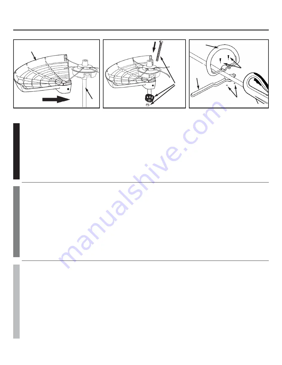
NOTE: The only assembly required for your trimmer is to install the debris shield and adjust the assist handle.

3-1. DEBRIS SHIELD INSTALLATION

1.

Position the motor housing with string head carrier facing up (Figure 3-1A).

2.

Place the debris shield (A) on the tube so the holes align with the slots on the bracket (B)(Figure 3-1B).

3.

Install the Shield knob and nut (C) and tighten securely.

3-2. “P” HANDLE ASSEMBLY

1.

To install handle onto unit, you will need the following components from your user kit: “P” handle (A & B), screws (C)
and nuts (D). (Figure 3-2).

2.

Install the handle (B) on the shaft and tighten the 2 screws (C) and nuts (D).

9

10

F

R

A

4.

POUR TOUT ENTRETIEN OU SERVICE AU TITRE DE LA GARANTIE, prenez contact avec le Centre de mainte-
nance agréé Troy Bilt le plus proche en appelant le numérogrtuit 800# mentionné sur le capot arrière.

1-3. SYMBOLES INTERNATIONAUX

1.

Lire la Notice d'utilisation (Figure 2-1).

2.

Il est fortement recommandé de respecter les consignes de sécurité personnelle pour réduire les risques d'accident
ou de blessures (Figure 2-2).

CONSERVER CES INSTRUCTIONS

E

N

G

4.

FOR WARRANTY OR SERVICE contact the nearest Troy Bilt Authorized Service Centerby calling 800# on back
cover.

1-3. INTERNATIONAL SYMBOLS

1.

Read the User Manual (Figure 2-1).

2.

Use of these personal safety items is highly recommended to reduce the risk of accidental injury (Figure 2-2).

SAVE THESE  INSTRUCTIONS

E

S

P

4.

PARA LA GARANTIA O EL SERVICIO póngase en contacto con el Centro de Servicio Autorizado de Troy Bilt lla-
mando al número 800# de la cubierta posterior.

1-3. SIMBOLOS INTERNACIONALES

1.

Lea el manual del Usuario (Figura 2-1).

2.

El uso de estos párrafos sobre seguridad personal es altamente recomendado para reducir el riesgo de heridas acci-
dentales (Figura 2-2).

CONSERVE ESTAS INSTRUCCIONES

Use of these personal safety items is highly recommended to
reduce the risk of accidental injury.

L’utilisation des ces dispostifs de sécurité est foretement recom-
mandé afim de réduire tout risque de blessures accidentelles.

El uso de estos articulos de seguridad personal es altamente
recomendado para reducir el riesgo de lesiones accidentales.

2-INTERNATIONAL SYMBOLS - SYMBOLES INTERNATIONAUX

SIMBOLOS INTERNACIONALES

Read the User Manual.
Lire le manuel d’utilisation.
Lea Manual de Usuario.

2-1

2-2

3 - ASSEMBLY INSTRUCTIONS - INSTRUCTIONS POUR MONTAGE -

INSTRUCCIONES DE ENSEMBLADO

F

R

A

N

C

A

I

S

NOTA : Le seul assemblage requis avant d'utiliser ce coupe-herbe est la pose du pare-débris et le réglage de la poignée
de maintien.

3-1. INSTALLATION DU PARE-DÉBRIS

1.

Positionner le carter du moteur de manière que la tête de coupe soit orientée vers le haut (Figure 3-1).

2.

Installer le pare-débris (A) sur le manche de manière à ce que les orifices soient alignés avec les encoches de la
patte de fixation (B) (Figure 3-1B).

3.

Placer la vis, rondelle et l’écrou (C) et serrer fermement.

3-2. “P” ENSEMBLE POIGNÉE

1. Pour installer la poignée sur l'unité, vous aurez besoin des composants suivants de votre kit utilisateur : Poignée “P” (A

& B), vis (C) et écrous (D). (Fig. 1)

2. Installez la poignée P (B) sur l'axe et suivez la flèche sur l'autocollant (étiquette de mise en garde E ), placer la poignée

(A) et serrez les deux vis (C) et écrous (D).

E

S

P

A

Ñ

O

L

NOTA: El único ensamblaje requerido para su recortadora es la instalación del protector de desechos y para ajustar el

manubrio auxiliar.

3-1. INSTALACION DEL PROTECTOR DE DESECHOS

1.

Coloque el bastidor del motor con el transportador de la cabeza de hilo viendo hacia arriba (Figura 3-1).

2.

Coloque el protector de desechos (A) sobre el tubo, de manera que los hoyos se alíneen con las ranuras en el
soporte (B) (Figura 3-1B).

3.

Instale el tornillo y la rondana (C) a través del protector. Coloque la tuera en la ranura de para la misma y ajuste el
tornillo seguramente.

3-2. ENSAMBLAJE DEL ASA “P”

1.

Para instalar el asa en la unidad, necesitará los siguientes coponentes desde el kit de usuario: Asa “P” ( A & B),
tornillos (C) y tuercas (D). (Figure 3-2)

2.

Instale el asa (B) en la cuchilla 160-200mm desde el acelerado y coloque los 2 tornillos (C) y tuercas (D).

3-1A

A

B

3-1B

C

3-2

A

B

C

D

Summary of Contents for TB65REX

Page 1: ...personal injury Spend a few moments to familiarize yourself with your trimmer before each use AVERTISSEMENT LIRE ATTENTIVEMENT Pour votre sécurité lisez entièrement ce manuel avant d utiliser votre nouvel outil Le non respect des instructions peut résulter en des accidents graves Prenez quelques instants pour vous familiariser avec le coupe herbe avant chaque utili sation ADVERTENCIA FAVOR DE LEER...

Page 2: ...ormation to highlight a particular explanation or expand a step description A WARNING or CAUTION identifies a procedure which if not undertaken or if improperly done can result in serious personal injury or damage to the unit and or both The WARRANTY SYMBOL serves notice that unless instructions or procedures are followed any damage caused will void the war ranty and repairs will be at owner s exp...

Page 3: ...lle de ligne ø0 08 2 0mm Poids Net 4 3 Kg 9 5 Lbs E N G SPECIFICATIONS TB65REX Input 120V 60Hz 6 75Amp No Load Speed 7 600 min Cutting width 14 355mm Line Diameter ø0 08 2 0mm Net Weight 4 3 Kg 9 5 Lbs E S P ESPECIFICACIONES TB65REX Potencia 120V 60Hz 6 75A Velocidad no Instalada 7 600 min 1 RPM Diámetro del Círculo de Corte 14 355mm Reserva del la línea ø0 08 2 0mm Peso neto 4 3 Kg 9 5 Lbs ...

Page 4: ...SING CARTER MOTEUR CAJA DEL MOTOR PLUG FOR EXTENSION CORD PRISE POUR RALLONGE ENCHUFE DE CABLE PROLONGADOR CORD RETAINER RETENUE DU CORDON RETENEDOR DEL CABLE ON OFF TRIGGER MANETTE MARCHE ARRET GATILLO DE ENCENDI DO APAGADO REX STRING HEAD REX TÊTE DE COUPE REX CABEZA DE HILO DEBRIS SHIELD PARE DEBRIS PROTECTOR DESECHOS SHAFT MANCHE MANGO ATTACHMENT COUPLER COUPLEUR D ACCESSOIRE ENGANCHE DE ACOPL...

Page 5: ... result in electrical shock burns fire or personal injury WARNING 1 1 TO REDUCE THE RISK OF ELECTRIC SHOCK BURNS FIRE OR PERSONAL INJURY 1 FOLLOW ALL SAFETY INSTRUCTIONS listed in this manual before during operation of this trimmer 2 TO REDUCE THE RISK OF ELECTRIC SHOCK this equipment has a polarized plug one blade is wider than the other This plug will fit in a polarized extension cord only one w...

Page 6: ...are chipped cracked or damaged in any way Keep cutter knife sharp 4 DOUBLE INSULATED to help protect against electric shock Double insulation construction consists of 2 sep arate layers of electric insulation Appliances built with this insulation system are not intended to be grounded As a result the extension cord used with your unit can be plugged into any conventional 120 volt electrical outlet...

Page 7: ... close door on cord 6 NO SERVICEABLE PARTS INSIDE Your double insulated appliance has no serviceable parts inside Do not attempt to repair it yourself For service information contact the Troy Bilt Product Service Department listed on the back cover of this User Manual 7 RISK OF EYE INJURY Always wear goggles or other suitable eye protection when operating your trimmer Edging increases the risk of ...

Page 8: ...me 11 AVOID A DANGEROUS ENVIRONMENT Do not use in the presence of flammable liquids or gases smoking or burning materials to avoid creating a fire or explosion Never operate the trimmer in wet or damp conditions or around swimming pools hot tub etc Do not use in rain Do not handle plug cord or appliance with wet hands 12 USE APPLIANCE CORRECTLY Use this appliance only for its intended use as descr...

Page 9: ...ob better and witth less likelihood of a risk of injury at the rate for which it was designed 1 2 EXPLANATION OF NOTE WARNING and WARRANTY SYMBOL 1 A NOTE is used to convey additional information or highlight a particular explanation or to expand a step instruc tion 2 A WARNING identifies a procedure which if not undertaken or if improperly done can result in a serious personal injury or damage to...

Page 10: ...Figure 2 2 SAVE THESE INSTRUCTIONS E S P 4 PARA LA GARANTIA O EL SERVICIO póngase en contacto con el Centro de Servicio Autorizado de Troy Bilt lla mando al número 800 de la cubierta posterior 1 3 SIMBOLOS INTERNACIONALES 1 Lea el manual del Usuario Figura 2 1 2 El uso de estos párrafos sobre seguridad personal es altamente recomendado para reducir el riesgo de heridas acci dentales Figura 2 2 CON...

Page 11: ...s de la patte de fixation B Figure 3 1B 3 Placer la vis rondelle et l écrou C et serrer fermement 3 2 P ENSEMBLE POIGNÉE 1 Pour installer la poignée sur l unité vous aurez besoin des composants suivants de votre kit utilisateur Poignée P A B vis C et écrous D Fig 1 2 Installez la poignée P B sur l axe et suivez la flèche sur l autocollant étiquette de mise en garde E placer la poignée A et serrez ...

Page 12: ...ition the unit with the string head carrier facing up 3 Align disposable string head locking tabs with corresponding slots in carrier as shown Figure 3 3A 4 With firm pressure push disposable string head onto carrier until an audible click is heard REMOVAL 1 Unplug unit 2 Press yellow button on side of string head to eject used REX disposable string head Figure 3 3B E S P A Ñ O L 3 3 INSTALACION Y...

Page 13: ...ement dans le coupleur à changements rapides jusqu à ce que le bouton de dégagement apparaisse dans le trou primaire du coupleur à changements rapides Fig 3 4B 3 Tournez le bouton dans le sens des aiguilles d une montre pour serrer Fig 3 4C ATTENTION Le bouton de dégagement doit être dans le trou primaire et le bouton serré solidement avant d actionner cette unité Tous les accessoires sont conçus ...

Page 14: ...ORD 1 Ensure the cord is NOT plugged into a receptacle before this procedure 2 Make a loop with 8 10 20 25cm of the end of the extension cord 3 Place the loop into the slots A under the motor housing and lock into place as shown in Figure 4 1 4 Connect the extension cord to the trimmer 5 Plug the extension cord into a receptacle ONLY when you are ready to operate the trimmer E S P 4 1 CONECTE EL C...

Page 15: ...t ahead with a slight tilt so bottom of stringhead is above ground level and string contact occurs at proper cutting point Always cut away from operator Do not pull trimmer in toward operator 3 FENCE FOUNDATION TRIMMING Approach trimming around chain link fences picket fences rock walls and foun dations slowly to cut close without whipping string against the barrier If the string comes in contact ...

Page 16: ... this tilt the stringhead to about a 30 degree angle to the left By adjusting the handle you will have better control during this operation Always keep a distance of 50 feet 15 meters from other people and animals when scalping Do not attempt this procedure if there is any chance flying debris could injure operator other people or cause damage to property 6 SWEEPING DO NOT SWEEP WITH TRIMMER Figur...

Page 17: ...SE ONLY THE STRINGHEAD SUPPLIED WITH THIS PRODUCT DO NOT USE ANY OTHER CUTTING ATTACHEMENT POUR DES RAISONS DE PERFORMANCES ET DE SÉCURITÉ UTILISEZ EXCLUSIVEMENT DES DES PIÈCES DE RECHANGE ET ACCESSOIRES D ORIGINE N UTILISER QUE LA TETE DE COUPE FOURNIE AVEC CE PRODUIT NE PAS UTILISER D AUTRES ACCESSOIRES DE COUPE POR RAZONES DE SEGURIDAD Y RENDIMIENTO UTILICE ÚNICAMENTE ACCESORIOS Y PIEZAS DE REP...

Page 18: ...epairs Doing so could create a hazard and void the manufacturer s warranty 2 Unplug the power cord before cleaning or performing maintenance or removing or installing REX string head 3 Never douse appliance with liquid or squirt with a garden hose Clean with a damp sponge 4 Keep air openings on the motor housing free from any debris to avoid overheating E S P A Ñ O L 6 1 CABEZA DE HILO 1 Use exlus...

Page 19: ...608 HANDLE ASS Y 18 8 6SDAB 05 12 SCREW 11 1 6SHDB 06 52 SCREW 18 9 9189 332101 GEAR SPRING 11 2 6NBB 06 NUT 19 11 3 6WFB 06 WASHER 19 1 6035 230301 LOCK NUT 11 4 9068 332601 HANDLE 19 2 6SXDB 06 30 SCREW 12 6028 230303 TRIGGER 19 3 6RZ04 08S RIVET 13 6NAB 06 NUT 19 4 6RZ04 06 RIVET 14 6056 230302 KNOB 19 5 6005 230302 KEEPER 15 6SXDB 06 60 SCREW 19 6 9228 A10112 BAG FRONT 16 6262 230301 GUARD 19 ...

Page 20: ...ht to change or improve the design of any Troy Bilt Product without assuming any obliga tion to modify any product previously manufactured No implied warranty including any implied warranty of merchantability or fitness for a particular purpose applies after the applicable period of express written war ranty above as to the parts as identified No other express warranty or guaranty whether written ...

Page 21: ...pour autant assumer l obligation de modifier tout produit d une fabrication plus ancienne Aucune garantie implicite y compris toute garantie de valeur marchande ou d adaptation à une fin particulière ne s applique après la période applicable de garantie expresse écrite ci dessus concernant les pièces qui sont identifiées Aucune autre garantie ou caution expresse écrite ou orale à l exception de ce...

Page 22: ...ión para modificar cualquier producto fabricado con anterioridad Ninguna garantía implícita es aplicable después del período de aplicabilidad de la garantía expresa escrita con anterioridad incluyendo cualquier garantía implíci ta de comerciabilidad o idoneidad para un propósito particular con respecto a las piezas identificadas Exceptuando lo mencionado anteriormente ninguna otra garantía expresa...

Page 23: ...DONOTreturn thisproducttothestore Contactyour CustomerServiceAgent Encasdeproblèmesoupourdesquestions NEPASretournerceproduitaupointdevente S adresser aupréposéduServiceàlaclientèleencomposant Paraproblemasopreguntas NOdevolveresteproductoalatienda ContacteasuAgentedeServicioalCliente U S A 1 800 520 5520 CANADA 1 800 668 1238 For Consumer Assistance Please Call L Aide Du Consommateur Necessitez S...

Reviews: