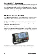
TractionAir
4
ECU Installation
1.
Mount the ECU in a position in the cab of the vehicle, where it will be
easily accessible for making pressure adjustments whilst driving
the vehicle.
2.
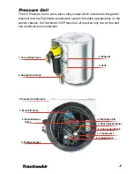
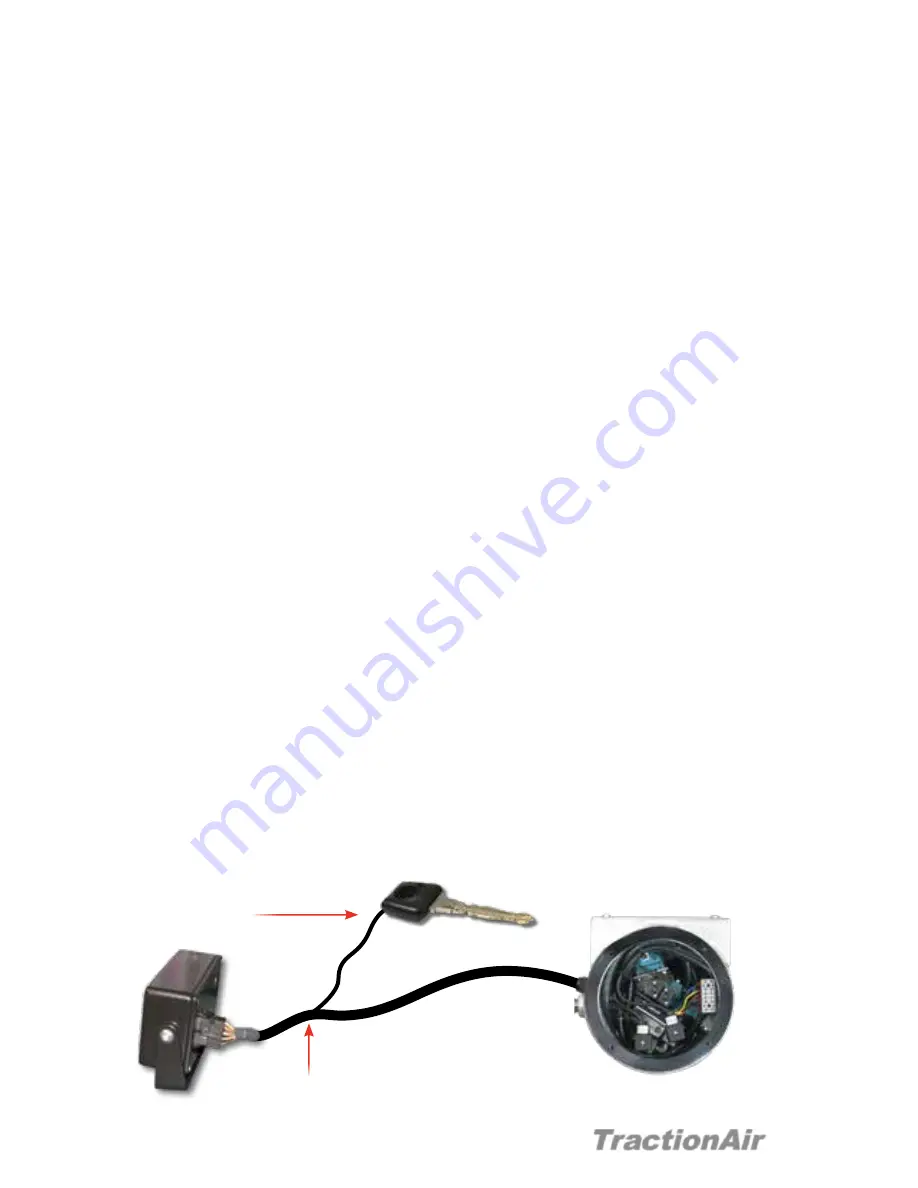
The rear of the ECU has a male electrical connector which connects to
the MOLEX Mini-Fit plug on the dual loom assembly. The two-core
power loom is to be wired into an auxiliary circuit which is isolated when
the ignition key is switched off. The other multicore loom is wired into the
pressure cell. (Power on with ignition, power off with ignition). The system
is suitable for both 12V and 24V vehicles and will operate between
11V to 30V DC.
a.
The short loom is the power supply comprising of two wires
(refer to ECU wiring diagram on pages 5). The ECU must be
protected with either a 2 amp blade fuse located in the fuse board
in the vehicle or by using the in-line 2 or 3 amp fuse provided in the
kitset.
b.
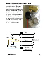
Run the long loom from the ECU to the alloy pressure cell.
It is important that sufficient length of cable is allowed for with cab-
over vehicles, to allow for tilting the cab. Use the convolute
steering to protect the cable.
c.
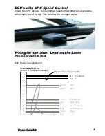
Attach the lead for the externally connected GPS unit to the
Female DIN plug on the rear of the ECU and site to suit within
the cab (as close to windscreen as possible).
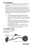
Connect Larger Loom to Pressure Cell
Connect Smaller
Loom to Ignition
10 Pin Female Plug
(To Rear of TIDD - TPC Controller)
2 Core Power (3m) to Ignition
7 Core to Pressure
Summary of Contents for TractionAir
Page 27: ...TractionAir 27...


