24
MEASURING CASTER, CAMBER AND SAI ON A
NON-LEVEL SURFACE
When the vehicle is not on a level surface, the procedure is somewhat different. The TR-30 Easy
Check Angle Gauge is used in conjunction with the TR-44 Level Compensator Bar to correct the
readings. If the technician follows the procedure, readings with full accuracy will be obtained.
Even though the measurements are accurate, the ground should be reasonably near level to assure
that the vehicle suspension is not affected.
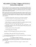
Before using the TR-44, it must be assembled and calibrated (refer to Figure 12). Figure 13 shows
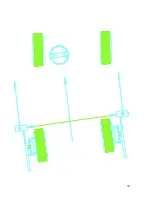
the bar placed under the front wheels of the vehicle to be measured. Since the bar rests near the
front wheels, it is tilted the same amount as the vehicle. The compensation procedure that follows
corrects for the tilt. After assembly, the bar is calibrated according to the following procedure
(refer to Figure 12):
1) Mount TR-28 Wheel Clamps on front wheels, or Hub Adapters (both sides).
2) Raise wheel and adjust run-out using the standard procedure (both sides)
3) Lower wheel onto turn table and remove locking pin (both sides)
4) Place TR-44 Level Compensator Bar (that has been assembled to match the tread
width and is calibrated) in front of wheels as shown in the Figure 13.
5) Beginning on the left side, hang TR-30 Easy Check Angle Gauge on the
mounting disk on the left side of the Level Compensator Bar and adjust camber zero knob
to zero the camber bubble.
6) Measure camber on the same left of the vehicle
7) Repeat steps 5 and 6 on the right side.
Remember to zero the camber gauge each time before you measure camber.
TO MEASURE CASTER AND SAI ON A NON-LEVEL SURFACE:
To correct the caster and SAI readings, the tilt of the vehicle must be known. The following
procedures will help find these values.
TO MEASURE THE SIDE TO SIDE TILT
SAI readings are affected by the side to side tilt of the vehicle. The following procedure
compensates for the tilt to give full accuracy SAI readings. You can make the SAI readings first, or
after this procedure.
1) Place the bar in front of the wheels as shown in Figure 13 with the red side on
the right side.


