background image

12 

use the procedure described in 

Installing and testing an earth system

 on 

page 9. 

Check the fence system for faults. 

The most common source of low 

voltage is faults on the fence line. 
If the fence, earth and energizer are in good condition and the voltage 
is still below 4 kV, talk to your nearest reseller. Recent extensions to 
your fence, a poor fence layout, or soil conditions may be causing 
inadequate voltage.  

How do I locate faults?


The recommended tool for locating faults is a Fault Finder or remote 
control handset. These have a combined voltage and current meter 
which allows you to rapidly locate sources of current leakage. 
Alternatively, use a Digital Voltmeter. Use cut-out switches to turn off 
the power to different sections of the farm. If the voltage on the fence 
increases when a section of the farm is turned off, then investigate that 
section for possible faults. 

There are no lights flashing on the energizer


Ensure the power supply is on. Check the fence system for faults (see 
above). Check the energizer (see above). If the energizer still does not 
operate, it may require servicing. 

The energizer does not respond to commands from the remote 

control handset 

See the Frequently Asked Questions/Troubleshooting section in the 
remote control handset’s user manual. 

I want to disable the energizer’s remote control feature 

If you have a remote control handset, see the remote control handset’s 
user manual for instructions. If not, take the energizer to an authorised 
service centre to have the feature disabled. 


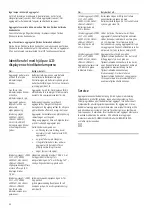
Identifying faults using the LCD display 
and the indicator lights 

If... 

This means that... 

The energizer is not pulsing 
and the first red Indicator light 
is flashing... 

The battery connections may be faulty. 
Check all battery connections. Check the 
battery voltage immediately using the 
battery test setting. See 

Testing the 

battery voltage

 on page 6. 

The first red Indicator light is 
flashing and other indicator 
lights are on... 

The energizer has a fault. If the display 
persists and does not return to normal, 
contact your service agent for advice. 

The energizer is pulsing slowly 
and has a reduced output 
voltage... 

The battery voltage may be low and the 
energizer has reverted to Slow Speed and 
Low Output Power in order to preserve 
the remaining power and energy in the 
battery. 

If... 

This means that... 

(6000i-EU, X6i-EU, 406i-EU, 

6000-EU, X6-EU and 406-EU 

energizers only)  

The warning light is flashing 
and a warning buzzer is 
sounding… 

The energizer has detected a sudden 
increase in the load on the fence.  
Switch the energizer off, locate and 
remedy fault then turn the energizer on 
again.  
For example, this may occur: 


if a cutout switch is closed, 
connecting a heavily loaded section 
of the fence to the energizer 


if a branch falls on the fence 


if the fence or cable connecting 
energizer to it experiences a sudden 
short to ground 


if something becomes entangled in 
the fence.  

(12000i, X12i, 412i, 6000i, 

6000i-EU, X6i, X6i-EU, 406i 

and 406i-EU energizers only)  

The output voltage digits (large 
digits on the LCD display) flash 
1.0 kV... 

The fence voltage is below 1000 V. There 
is a serious fault on the fence line. See 
“How do I locate faults?” in 

Frequently 

asked questions/Troubleshooting

 on 

page 11. 

(12000i, X12i, 412i, 6000i, 

6000i-EU, X6i, X6i-EU, 406i 

and 406i-EU energizers only) 


The first red Indicator light is 
illuminated permanently... 

The earth monitor voltage is too high. 
Use the earth monitoring feature to 
monitor the earth. See 

Earth monitoring


on page 5. 

(12000i, X12i, 412i, 6000i, 

6000i-EU, X6i, X6i-EU, 406i 

and 406i-EU energizers only)  

The battery symbol on the LCD 
is flashing... 

The battery voltage is bad. Check the 
battery voltage immediately, using the 
battery test setting. See 

Testing the 

battery voltage

 on page 6. 

(12000i, X12i, 412i, 6000i, 

6000i-EU, X6i, X6i-EU, 406i 

and 406i-EU energizers only)  

The right arrow on the LCD is 
flashing... 

During the first 10 minutes of operation, 
the energizer’s remote control feature 
can be activated. During this period, the 
large arrow on the LCD display flashes to 
indicate this. This occurs each time the 
energizer is switched on when the 
energizer’s remote control feature has 
not been activated This is part of normal 
operation.  

(12000i, X12i, 412i, 6000i, 

6000i-EU, X6i, X6i-EU, 406i 

and 406i-EU energizers only)  

The energizer is not pulsing 
and the last green Indicator 
light is flashing... 

The energizer has been switched off by a 
remote control handset. If you think your 
energizer might be being controlled by a 
neighbour’s remote control handset and 
you own a remote control handset 
yourself, change your energizer’s address 
setting (see the remote control handset’s 
user manual). If you do not have a 
remote control handset, take the 
energizer to an authorised service centre 
to have the remote control feature 
disabled. 


Summary of Contents for Unigizer 12000i

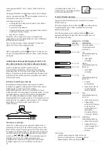
Page 1: ...ences An electric fence is not only a physical barrier but is also a strong psychological barrier What are the benefits of an electric fence An electric fence has many benefits over conventional fencing Requires less labour and materials to construct Flexibility to change or add paddocks when required The use of strip grazing techniques can allow temporary fencing to be quickly and easily erected ...

Page 2: ... the risk of electric shock the energizer s power adaptor may have a polarized plug one blade is wider than the other This plug will fit in a polarized outlet one way If the plug does not fit fully in the outlet reverse the plug If it still does not fit contact a qualified electrician to install the proper outlet Do not change the plug in any way Switch the energizer off before installation or per...

Page 3: ...lip to the positive terminal of the battery and the black clip to its negative terminal Note If the energizer is to be used as part of a permanent outdoor installation such as a solar installation the battery lead clips should be replaced by permanent battery connectors To remove the battery leads 1 Remove the clips from the battery terminals 2 Hold the battery lead by the rubber sleeve at the end...

Page 4: ...e energizer with mains line power if it is being installed outdoors USA Canada Refer to Important safety instructions for Class 2 power units USA Canada only on page 11 To install the energizer as part of a solar installation 1 Select a suitable installation site See Selecting a site for the installation on page 3 For solar installations it is also important to select a site where the solar panel ...

Page 5: ...egments are illuminated at each pulse the output voltage is approximately 8 kV 8000 V Red Green 1 2 3 4 5 6 7 8 9 10 kV Note If ten Indicator light segments are illuminated the output voltage may be more than 10 kV 10 000 V If you see only red lights at each pulse and no green lights your fence line is very heavily loaded and you will need to look for faults on the fence line See Frequently asked ...

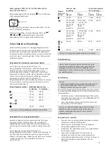
Page 6: ...slow speed 2 5 seconds between pulses and the fence is live Lights Input supply voltage Battery only installation Above 17 0 V Abnormal conditions check battery and connections 12 6 V 17 0 V Full battery charge voltage 80 100 No action required or 12 3 12 6 V 12 0 12 3 V Medium battery charge voltage 50 80 No action required 11 7 12 0 V Low battery charge voltage 20 50 Monitor battery voltage Rech...

Page 7: ...Ah Warning 12 V rechargeable batteries must be used Battery management Warning Batteries contain harmful chemicals and when used incorrectly may cause injury Observe the guidelines for battery care maintenance and safety in this manual and in the documentation supplied with your battery Battery charging Warning Do not attempt to recharge a non rechargeable battery When recharging a battery ensure ...

Page 8: ... fence system comprises the following elements An energizer An earth system This comprises a number of metal rods inserted into the ground which are connected to the Fence earth terminal on the energizer Insulated underground cables Electric fence wire coated in insulated plastic suitable for use underground or going through walls Used to connect the energizer to the earth and fence An insulated f...

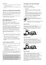
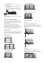
Page 9: ...er firmly setting the footed strainer in the ground dig in the stay block just below ground level at a distance to ensure the angle stay will be held snugly in position The stay can be levered into position with a spade All live system Fence return system Horizontal stay Suitable for field gate high tension strainer Very simple to erect and most suitable as a high tension strainer excellent in are...

Page 10: ...rier not less than 1 5 m 5 high intended to prevent inadvertent contact with the pulsed conductors of the electric fence Physical barriers are typically constructed from vertical sheeting rigid vertical bars rigid mesh rods or chainwire mesh Requirements for electric animal fences Electric animal fences and their ancillary equipment shall be installed operated and maintained in a manner that minim...

Page 11: ...onnected to the electric animal fence circuit provides a degree of isolation between the fence circuit and the supply mains equivalent to that provided by the energizer Protection from the weather shall be provided for the ancillary equipment unless this equipment is certified by the manufacturer as being suitable for use outdoors and is of a type with a minimum degree of protection IPX4 Important...

Page 12: ...d energy in the battery If This means that 6000i EU X6i EU 406i EU 6000 EU X6 EU and 406 EU energizers only The warning light is flashing and a warning buzzer is sounding The energizer has detected a sudden increase in the load on the fence Switch the energizer off locate and remedy fault then turn the energizer on again For example this may occur if a cutout switch is closed connecting a heavily ...

Page 13: ...D and or the symbol below Product specifications 6 J models 12 J models Power supply 12 V battery or approved power adaptor 100 120 V or 100 240 V Power consumption using a power adaptor 10 W 15 W Current consumption using a 12 V rechargeable battery Battery Test 410 mA 700 mA Slow Speed Day Fast Speed Night 410 mA day 650 mA night or 530 mA 24 hour average 700 mA day 1100 mA night or 900 mA 24 ho...

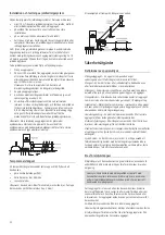
Page 14: ...tet Stängslets jordningsuttag Anslut stängslets jordningsuttag till aggregatets jordningssystem Stängslets jordningsövervakningsuttag endast aggregat 12000i X12i 412i 6000i 6000i EU X6i X6i EU 406i och 406i EU Anslut stängslets jordningsövervakningsuttag till en separat jordningsstake Se Jordningsövervakning på sidan 18 Stängslets halvspänningsuttag För användning i områden med dålig jordning se B...

Page 15: ...lutning till nät ledningsström och en uppsättning batteristift för anslutning till ett batteri Innan en strömadapter eller batteristift ansluts säkerställ att aggregatets väljarbrytare är inställd på Av För att använda strömadaptern 1 Anslut strömadaptern till strömingångsuttaget på baksidan av aggregatet 2 Anslut strömadaptern till ett lämpligt nät ledningsuttag och försäkra dig om att det finns ...

Page 16: ...rdningssystem 4 Endast aggregat 12000i X12i 412i 6000i 6000i EU X6i X6i EU 406i och 406i EU Om jordningsövervakning önskas anslut stängslets jordningsövervakningsuttag svart till en separat jordningsstake För mer information se Jordningsövervakning på sidan 18 5 Anslut stängslets helspänningsuttag rött eller stängslets halvspänningsuttag gult till stängslet 6 Anslut aggregatet till batteriet med d...

Page 17: ...r på natten När denna inställning används drivs aggregatet med full energi Denna inställning är för djur som är aktiva på natten och är ett lämpligt sätt att spara på batteriet när ett batteri används för att ge energi åt aggregatet Snabb hastighet dag Långsam hastighet natt Aggregatet drivs med snabb hastighet 1 5 sekunder mellan pulser på dagen och långsam hastighet 2 5 sekunder mellan pulser på...

Page 18: ...g Se till att isoleringen skalas tillbaka för att få god kontakt mellan tråden och jordledningsstaven Övervakning av jordningen Om den första indikatorlampan lyser permanent indikerar detta att jordspänningen är över 0 8 kV och att bättre jordning kan vara till en fördel Använd antingen fler jordningsstavar eller hitta en bättre plats för aggregatets jordledningssystem De små siffrorna på LCD disp...

Page 19: ...ler inget solljus Den tar med olika solpanels och regulatortyper i beräkningen som skulle kunna användas i solpanelsinstallationen För mer detaljerad information se www tru test com Väljarom kopplarens position Ström som krävs ungefärlig Minsta batterikapacitet 80 urladdning 6 J modeller 12 J modeller 6 J modeller 12 J modeller 410 mA 700 mA 110 Ah 190 Ah 410 mA dag 650 mA natt 530 mA 24 timmars g...

Page 20: ... återaktiveras efter ett strömavbrott även om det stängdes av av den fjärrkontrollerade handenheten innan strömavbrottet Stängslet måste alltid anses vara strömförande oavsett aggregatets omkopplarposition eller fjärrkontrollens status Om du arbetar på ett stängselavsnitt isolera avsnittet med en strömbrytare eller koppla bort aggregatet från strömkällan Att bygga ett permanent elstängsel Komponen...

Page 21: ...ttag gult används överskrider stängslets spänning inte 5 kV men utgångsströmmen förblir densamma Stängselutföranden Stängsel kan konstrueras så att de passar boskapstypen och tillgängliga material Rådgör med återförsäljaren om vilket utförande som passar dina behov En del förslag på stängselkonfigurationer anges nedan Nötboskap och hästar 10 15 m mellanrum enbart stolpar 15 20 m mellanrum med mell...

Page 22: ...r bättre sikt krävs t ex hästar Ett exempel på ett temporärt stängsel visas nedan Säkerhetsåtgärder Definitioner av specialuttryck Elstängselaggregat En apparat som periodvis avger spänningsimpulser till ett stängsel som är anslutet till det Stängsel En barriär för djur eller i säkerhetssyfte bestående av en eller flera ledare såsom metalltrådar stavar eller räcken Elstängsel En barriär som innehå...

Page 23: ...tt elektriskt djurstängsel korsar en allmän stig ska en ej elektrifierad grind byggas in i det elstängslet vid den punkten eller också ska en korsning anordnas med hjälp av en stätta Vid en sådan korsning ska angränsande elektrifierade trådar vara försedda med varningsskyltar om elstängsel Alla delar av ett elstängsel som installeras längs en allmän väg eller stig ska identifieras med täta mellanr...

Page 24: ...ayen blinkar 1 0 kV Stängslets spänning är under 1 000 V Det har uppstått ett allvarligt fel i stängselledningen Se Hur hittar jag fel i Vanliga frågor Felsökning på sidan 23 Endast aggregat 12000i X12i 412i 6000i 6000i EU X6i X6i EU 406i och 406i EU Den första röda indikatorlampan lyser permanent Jordningsövervakningsspänningen är för hög Använd jordningsövervakningsfunktionen för att övervaka jo...

Page 25: ...r garantie wordt geclaimd stuur dit product dan met een bewijs van aankoop naar de zaak waar u het heeft gekocht Details van garantieperiodes en andere van toepassing zijnde voorwaarden zijn verkrijgbaar bij de zaak waar u het product heeft gekocht of bij www tru test com N B Er wordt geen aansprakelijkheid aanvaard voor ongevallen of schade die het gevolg zijn van manipulaties aan dan wel verande...

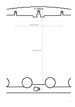
Page 26: ...51 130 mm 5 1 8 216 mm 8 1 2 6 J Unigizer ...

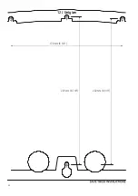
Page 27: ...52 170 mm 6 3 4 12 J Unigizer 225 mm 8 7 8 222 mm 8 3 4 ...

Reviews: