background image


TRU-TURF R52-ELT

 Golf Greens Roller Manual

45


TRU-TURF R52-ELT

 Golf Greens Roller Manual

46


AC Motor Controller Fault Code Troubleshooting

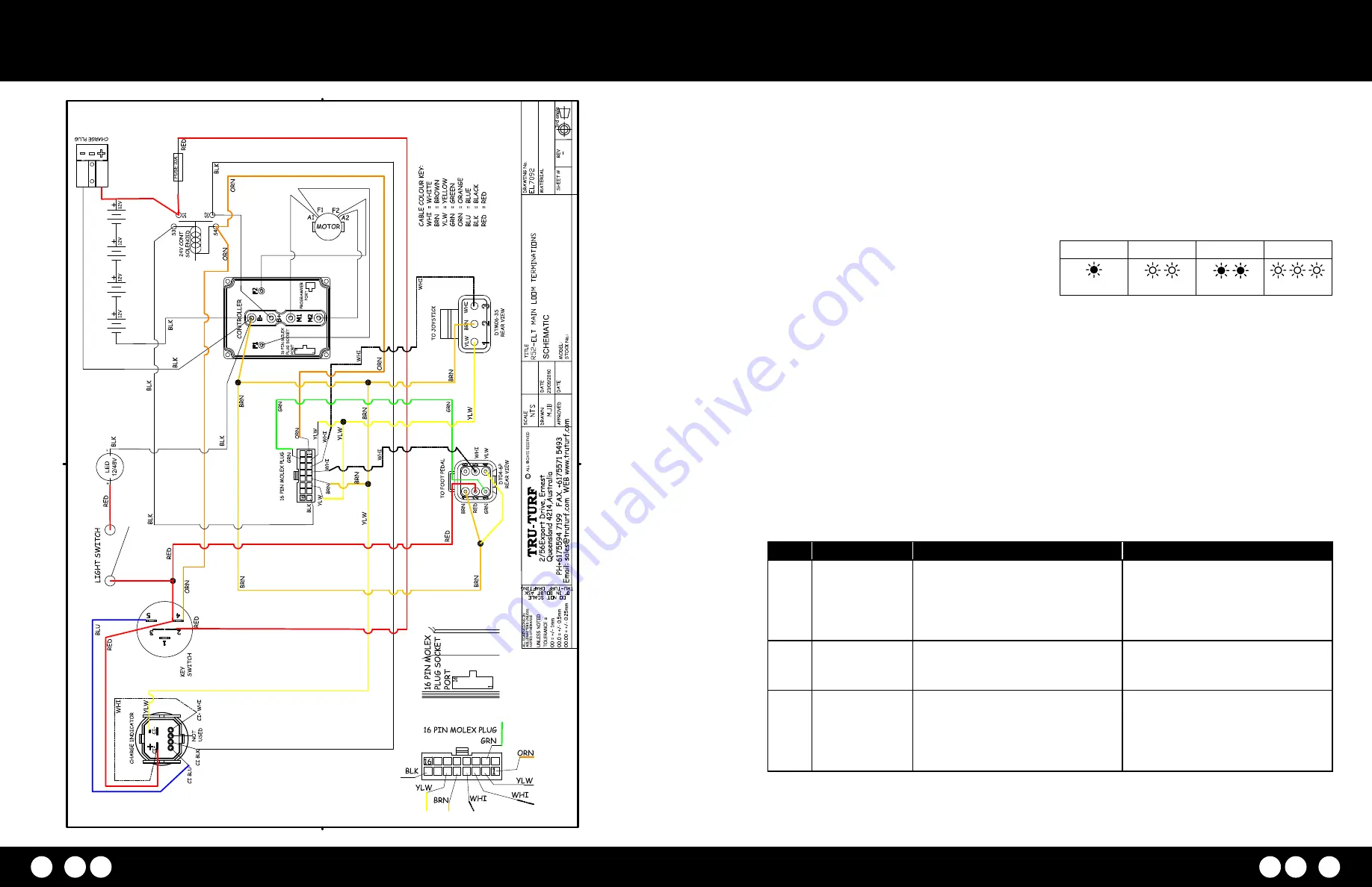
Loom Schematic Diagram

The instruction details and describes the process to 
read and interpret the fault codes displayed on the AC 
motor controller unit fitted to the AC electric models.

This information can be obtained by observing the fault 
codes issued by the Status LEDs.

The pair of LEDs built into the controller (one red, one 
yellow) produce flash codes displaying all the currently set 
faults in a repeating cycle.

Each code consists of two digits.

1.  The red LED flashes once to indicate that the first digit 

of the code will follow;

2.  The yellow LED then flashes the appropriate number of 

times for the first digit.

3.  The red LED flashes twice to indicate that the second 

digit of the code will follow;

4.  The yellow LED flashes the appropriate number of times 

for the second digit.

The numerical codes used by the yellow LED are listed 
in the following troubleshooting chart, which also lists 
possible fault causes and describes the conditions that set 
and clear each fault.

Example: 

Battery Under Voltage (code 23). The controllers 

LEDs will display this repeating pattern.

RED

YELLOW

RED

YELLOW

(First digit)

(2)

(Second digit)

(3)

Code

Fault Name

Possible Cause

Set/Clear Conditions

12

Controller over 
current

1.  External short of phase U,V or W 

motor connections.

2. Motor parameters are mistuned.
3. Controller defective.
4. Speed encoder noise problems.

Set: 

Phase current exceeded the 

current measurement limit.

Clear: 

Cycle KSI.

13

Current Sensor 
Fault

1.  Leakage to vehicle frame from phase 

U, V, W (Short in motor stator).

2. Controller defective.

Set: 

Contoller current sensors have 

invalid offset reading.

Clear: 

Cycle KSI.

14

Precharge Failed

1.  See Monitor menu > Battery: 

Capacitor Voltage.

2.  External load on capacitor bank (B+ 

connection terminal) that prevents 
the capacitor bank from charging.

Set: 

Percentage failed to charge the 

capacitor bank to the KSI voltage.

Clear: 

Cycle Interlock Input

Summary of Contents for R52-ELT

Page 1: ...R52 ELT ELECTRIC GOLF ROLLER MANUAL...

Page 2: ...10 Service of drive chain system 10 Lubrication 10 Service of smoothing roller bearings 10 Change transmission oil 11 Maintenance Schedule 11 FAULT FINDING 12 Roller will not move one or either way 1...

Page 3: ...all times 5 Change the transmission oil as per the transmission manufacturers servicing schedule Important Machine Information Model R52 ELT Golf Green Roller Serial No Purchase Date No Congratulatio...

Page 4: ...ground roller MT5000 1 MT5000 2 and MT5000 3 Totes are covered for a period of twelve 12 months Ensure that you the owner or the Dealer has lodged the completed Warranty Registration and Inspection Re...

Page 5: ...onto the axle until the circlip groove is revealed fit the circlip ensuring it is located in the groove correctly Step 3 Attaching draw bar to trailer arms Locate the draw bar assembly Gather the end...

Page 6: ...mately 4mph 7kph Towing at excess speed or across rough terrain may cause damage to the machine and trailer When approaching the green do not tow the roller onto the green to set up put the roller on...

Page 7: ...eness is detected replace the faulty bearings If bearings are faulty a Remove the complete smoothing head from the machine undo the four swivel mount bolts on upper body steering rod and stabilizer ro...

Page 8: ...efore installing the rollers into the heads in the correct sequence smaller diameter washer first and the larger diameter washer last f Sometimes if the rollers do not rotate freely when installed use...

Page 9: ...TRU TURF R52 ELT Golf Greens Roller Manual 13 TRU TURF R52 ELT Golf Greens Roller Manual 14 Park Brake System Operating Positions TOWING POSITION ROLLING POSITION CHARGE STORE POSITION...

Page 10: ...TRU TURF R52 ELT Golf Greens Roller Manual 15 TRU TURF R52 ELT Golf Greens Roller Manual 16 Park Brake Park Brake System...

Page 11: ...TRU TURF R52 ELT Golf Greens Roller Manual 17 TRU TURF R52 ELT Golf Greens Roller Manual 18 Cover Body Assembly Upper...

Page 12: ...er Manual 19 TRU TURF R52 ELT Golf Greens Roller Manual 20 Transmission Cover Latch Gauge Gauge Mount PRODUCED BY AN AUTODESK EDUCATIONAL PRODUCT PRODUCED BY AN AUTODESK EDUCATIONAL PRODUCT PRODUCED B...

Page 13: ...RF R52 ELT Golf Greens Roller Manual 21 TRU TURF R52 ELT Golf Greens Roller Manual 22 Computer Assembly Motor Gearbox PRODUCED BY AN AUTODESK EDUCATIONAL PRODUCT PRODUCED BY AN AUTODESK EDUCATIONAL PR...

Page 14: ...TRU TURF R52 ELT Golf Greens Roller Manual 23 TRU TURF R52 ELT Golf Greens Roller Manual 24 Transmission Underbody Assembly Lower...

Page 15: ...TRU TURF R52 ELT Golf Greens Roller Manual 25 TRU TURF R52 ELT Golf Greens Roller Manual 26 Flex Drive Roller Flex Drive Roller...

Page 16: ...TRU TURF R52 ELT Golf Greens Roller Manual 27 TRU TURF R52 ELT Golf Greens Roller Manual 28 Drive Roller Sprocket Bearings Joystick Steering Shaft...

Page 17: ...TRU TURF R52 ELT Golf Greens Roller Manual 29 TRU TURF R52 ELT Golf Greens Roller Manual 30 Rod Units Steering Assembly...

Page 18: ...TRU TURF R52 ELT Golf Greens Roller Manual 31 TRU TURF R52 ELT Golf Greens Roller Manual 32 Smoothing Head T Frame Smoothing Head...

Page 19: ...TRU TURF R52 ELT Golf Greens Roller Manual 33 TRU TURF R52 ELT Golf Greens Roller Manual 34 Trailer Frame Assembly Trailer Frame Assembly...

Page 20: ...TRU TURF R52 ELT Golf Greens Roller Manual 35 TRU TURF R52 ELT Golf Greens Roller Manual 36 Drawbar A Jockey Wheel...

Page 21: ...TRU TURF R52 ELT Golf Greens Roller Manual 37 TRU TURF R52 ELT Golf Greens Roller Manual 38 Hub Taper Axle Hub Parallel Axle...

Page 22: ...TRU TURF R52 ELT Golf Greens Roller Manual 39 TRU TURF R52 ELT Golf Greens Roller Manual 40 Option Drawbar Extension Kit Option Drawbar Extension...

Page 23: ...the battery see Fig 1 1 Place battery 1 onto the machine and locate into position attach foam rubber strips 1 2 to side and end of battery 2 Place battery 2 onto the machine and locate into position a...

Page 24: ...et Ensure the hose connecting end of the coupling is facing towards the front of the roller Do nut up firm do not over tighten the bracket 6 Use zip ties to secure tubing as shown Topping up battery w...

Page 25: ...r the second digit The numerical codes used by the yellow LED are listed in the following troubleshooting chart which also lists possible fault causes and describes the conditions that set and clear e...

Reviews:

Related manuals for R52-ELT