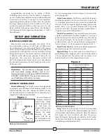
background image

4

TRUCKFORCE

®

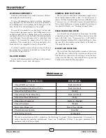
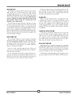
ACCESSING COMPONENTS

Drain the solution and waste tanks, disconnect all hoses,

and unplug the electrical cord(s).

To access the pump/motor, fresh water filter, and plumb-

ing components, lay the TruckForce on its back and remove
the 6 Phillips-head screws holding the bottom plate to the
body. Slowly lower the bottom plate to the ground.

To access the vacuum motors, cooling fan(s), switches, and

other electrial components: remove the 6 Phillips-head screws
on the back plate and the 3 Phillips-head screws securing the
switch plate. Slowly lower the back plate. When the back plate
is partially open, loosen and remove the vacuum hose from
vacuum #1 by loosening the clamp with a 5/16 driver or
screwdriver. This vacuum hose is not long enough to allow
the back plate to be completely lowered to the ground.

To retrun to operation, reverse the above steps. Make sure

the vacuum hose is properly re-installed on vacuum #1 and
that the hose clamp is secure.

FILL HOSE SCREEN

Located in the female garden hose fitting on the Automatic

Fill Hose. Remove screen, clean, and replace.

CHEMICAL FEED FOOT VALVE

The foot valve is on the end of the chemical supply tube of

the automatic chemical feed system. It is not necessary to
remove the filter from the tubing. Just rinse with fresh water.
If necessary, use a tooth brush to remove detergent build-up.
Note: a heavy build-up is a warning sign that the solution sys-
tem should be flushed—see “Flushing Solution System.”

FRESH WATER TANK FILTER

Located inside the bottom plate by the pump at the bottom

of the solution tank. Unscrew the filter counterclockwise and
rinse with fresh water. If necessary use a tooth brush to
remove detergent build-up. Note: a heavy build-up is a warn-
ing sign that the solution system should be flushed—see
“Flushing Solution System.”

WASTE TANK FILTER BAG

The waste tank filter bag should be cleaned out after every

job. This filter bag will catch the larger debris and most lint.
The filter bag is attached by a drawstring. Loosen the draw-
string, clean the filter bag, and reinstall. Never operate the
TruckForce without the filter bag in place.

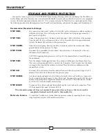
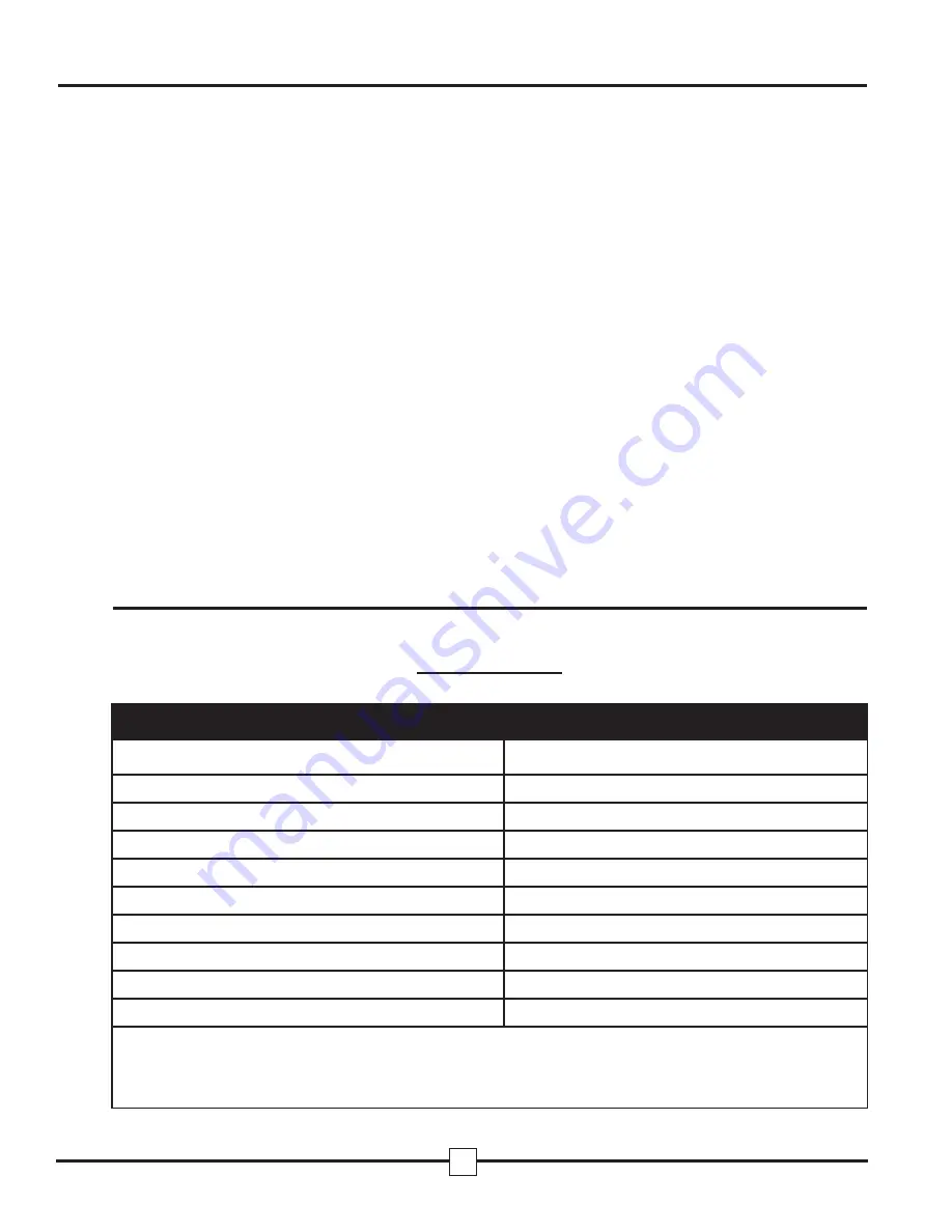
OPERATION

INTERVAL

Clean Fill Hose Screen

Each Job/Daily

Clean Chemical Feed Foot Valve

Each Job/Daily

Clean Fresh Water Filter

Weekly

Clean Waste Tank Filter Bag

Each Job/Daily

Clean Vac Shut Off Screen

Daily

Clean Auto Pump-out

Daily As Needed

Clean Wand Jets

Weekly

Run Auto Pump-out

Every Two Weeks

Flush Solution System

Monthly

WD-40 Vac Motors

As Needed

The above operations are fully outlined on the following two pages. Proper maintenance is necessary to
achieve maximum operating performance from your TruckForce. Failure to properly maintain your
machine could void the warranty.

Maintenance

MasterBlend

(800) 525-9644

Summary of Contents for 1200

Page 1: ...Operating and Maintenance Manual Models TruckForce 3500 TruckForce 1200 ...

Page 2: ... metering valve see Figure 1 Unscrew the colored metering tip and replace with the tip that corresponds to the portable dilution ratio for your cleaning product refer to Figure 2 Reconnect the plastic supply tube Liquid Concentrates TruckForce comes with the purple metering tip installed at the factory This tip is rated for 25 oz of chemical per gallon of water which is a standard dilu tion ratio ...

Page 3: ...lve located next to the pressure regulator on the front of the machine Making sure there is sufficient water in the solution tank depress the Power Prime Valve and any air will be immediately purged out of the pump system and pressure should immediately be restored Caution Please be aware that depressing the Power Prime Valve will also spray both air and water out the bot tom of the valve If you w...

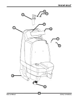
Page 4: ...ASSM 11 B SHUT OFF SPRING 12 C SHUT OFF PLATE 13 D SHUT OFF STEM O RING ITEM PART PART DESCRIPTION 14 E SHUT OFF COVER O RING 15 F SHUT OFF COVER 16 G STEM NUT WITH SET SCREW 17 H LEVER ASSEMBLY 18 I LEVER ASSEMBLY SCREWS 2 19 740119 RUBBER WASHER 20 740120 BACKFLOW PREVENTER 21 740121 PROPORTIONER 22 740122 METERING TIP KIT 23 740123 CHEMICAL SUPPLY TUBING 24 740124 FOOT VALVE 25 740125 DISCHARGE...

Page 5: ...th fresh water If necessary use a tooth brush to remove detergent build up Note a heavy build up is a warning sign that the solution sys tem should be flushed see Flushing Solution System FRESH WATER TANK FILTER Located inside the bottom plate by the pump at the bottom of the solution tank Unscrew the filter counterclockwise and rinse with fresh water If necessary use a tooth brush to remove deter...

Page 6: ...ughly unhook the vac uum cuff cut the zip tie around the looped electrical cord and lift it out of the waste tank Unsnap the screen from the bottom clean the screen and clean out the area inside If necessary remove the six screws holding the base to the motor housing and clean the base If the impeller is removed make sure that a spacing of 050 with shaft pushed toward housing is maintained when re...

Page 7: ...QD at the auto fill chemical feed connection CAUTION Applying high pressure over 100 psi to the chemical feed system will damage the mechanism STEP FIVE Place the chemical feed supply tube into the container with the pint of anitfreeze from Step One turn on the pump and allow to circulate for 10 minutes Check to make sure the chemi cal supply tube is drawing the antifreeze solution This will intro...

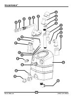
Page 8: ...LID W GASKET 740173 GASKET ONLY 740174 8 DECK LID ONLY 25 740218 1 FLOAT SHUTOFF ELBOW 26 740200 1 FLOAT BALL SHUTOFF 27 702905 3 HOSE CLAMP 2 1 4 28 18 740232 1 PUMPOUT ASSEMBLY W SWITCH 115V 28 18 740260 1 PUMPOUT ASSEMBLY W SWITCH 230V 29 705105 1 DRAIN VALVE NUT 2 30 740253 1 PVC 2 ELBOW WASTE BAG RET 31 740036 1 WASTE FILTER BAG 32 740214 1 WASTE TANK 33 740258 1 VAC HOSE VAC II TO MUFFLER 7 ...

Page 9: ...5022 1 REGULATOR 600PSI 3500 715023 PRESSURE REG KIT PISTON UCUP 68 715025 1 PRESSURE REG BACK PLATE 69 700307 8 ELBOW STREET 3 8 70 715024 1 PRESSURE REG FRONT PLATE 71 721122 1 PULSEHOSE 3 8 MPT X 3 8 FPT 72 721023 1 PULSEHOSE 3 8 FPT X 1 4 MPT 73 721221 1 PULSEHOSE 3 8 MPT X 1 4 FPT 74 740259 2 HOSE 1 2 CLEAR 9 SOLUTION PUMP 75 702902 2 HOSE CLAMP 1 2 76 77 78 79 740221 1 FRESH WATER FILTER 1 2...

Page 10: ...1 2 3 4 5 6 7 8 9 10 9 TRUCKFORCE MasterBlend 800 525 9644 ...

Page 11: ...20 21 22 19 23 24 25 26 11 27 28 29 30 31 32 9 11 12 13 14 18 17 19 16 15 10 TRUCKFORCE MasterBlend 800 525 9644 ...

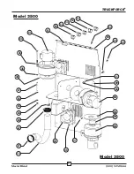
Page 12: ...51 52 53 53 53 53 54 50 44 45 35 49 34 46 38 39 46 47 42 10 27 27 34 34 35 35 37 35 40 41 35 38 48 11 TRUCKFORCE MasterBlend 800 525 9644 Model 3500 Model 3500 ...

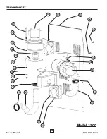
Page 13: ...12 TRUCKFORCE MasterBlend 800 525 9644 41 42 43 44 45 35 34 46 27 33 42 27 35 37 38 39 35 35 40 36 35 34 27 10 48 Model 1200 ...

Page 14: ...74 75 76 75 74 69 77 78 34 71 85 44 91 88 57 44 65 67 68 86 69 69 80 72 59 70 63 89 64 66 62 61 34 58 35 34 60 34 59 56 55 69 73 35 82 81 83 69 79 87 90 69 69 13 TRUCKFORCE MasterBlend 800 525 9644 ...

Page 15: ...KIT A KIT B KIT C 14 TRUCKFORCE MasterBlend 800 525 9644 1200 PSI Pump 500 PSI Pump Part 67 500 PSI Pressure Regulator 1200 PSI Unloader Valve ...

Page 16: ...15 TRUCKFORCE MasterBlend 800 525 9644 ...

Page 17: ...16 TRUCKFORCE MasterBlend 800 525 9644 ...

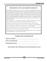
Page 18: ...epaid This warranty does not cover normal wear items such as hoses power cords filters gaskets valves quick disconnects and other parts that require replacement in ordinary use Replacement parts are warranted only for the remaining period of the original warranty This warranty is for the replacement of defective parts or workmanship only It does not pro vide for the replacement of entire units due...

Reviews: