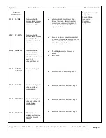
Symptom
Probable
Cause
Corrective
Action
Soft Select
Malfunctions
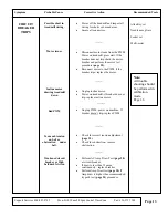
Control Panel Issues
Mechanical Issues
Incorrect/ Missing
Count Values
Defective Motor/
Start Capacitor
•
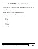
Enter calibration mode
•
Is there a count value displayed in the distance window? If No
replace control panel. If yes- continue to next step.
--------
•
Press and hold the softer button, release. Press and hold the firmer
button to detect carriage movement in both directions. If the carriage
cannot go full range from –220 and consistently stops in the same
place, check for mechanical binding. Inspect the under pan for
damage or areas that cause mechanical binding. Also inspect the
carriage track in the side frame for binding. If the carriage cannot
move to its full range and back in the time limit, check for
mechanical binding.
•
If the carriage is not moving and the motor is turning, check the set
screws holding the drive shaft to the motor shaft.
--------
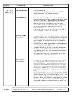
•
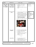
Threaded shaft turns when commanded but the pulse count does not
display/ or does not change. Physically check the hex cam located at
the front of the shaft and on the motor shaft. Hex cam should be
firmly attached. If hex cam slides freely super gluing it back onto the
shaft can repair it.
•
Hex cam moves but counter does not register. Ensure that the micro
switch is properly adjusted and the switch is being made when the
hex cam points press against the roller.
•
Disconnect the cable at J4 and check for continuity on cable. Cable
should have continuity if the switch roller is in a flat area of hex cam.
If no continuity- replace cable. If good continuity, place cable back
on J4 and continue
•
While in calibration mode place the multi-meter leads on J4 and
check for 5 Volts. If no 5 Volts- replace board.
--------
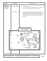
•
If command and count data/voltage are present and Led 1 indicates
AC voltage is good but soft select motor does not respond. Set
probes on TP 8 and TP3, press soft command (with soft select limit
switch not activated) result should be 120 VAC. Set probes on TP8
and TP2 and press firm command (with soft select limit switch not
activated) result should be 120 VAC. If no 120 VAC on either test
point- replace soft select board. If voltage is correct- continue to next
step.
•
In calibration mode, place red lead on the larger red wire and post on
the start capacitor of the soft select system and the black lead on the
common black lead, press firm- the result should be 120 VDC. Next
place the white lead on the larger white wire and post on the start
capacitor of the soft select system and the black lead on the common
black lead; press soft- the result should be 120 VDC. If voltage is
correct- replace the motor. If voltage is incorrect- replace the start
capacitor.
Support Services 800-883-8783
Mon-Fri 8:30am-5:00pm Central Time Zone
Fax: 636-272-7148
Page 14
Summary of Contents for 350 Black
Page 20: ...Page 18...
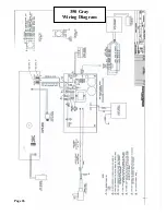
Page 28: ...Page 26 350 Gray Wiring Diagram...
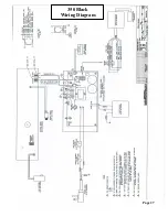
Page 29: ...Page 27 350 Black Wiring Diagram...
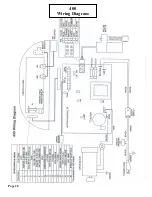
Page 30: ...Page 28 400 Wiring Diagram...
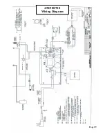
Page 31: ...Page 29 450 500 700 Wiring Diagram...
Page 32: ...Page 30 500CI 750CI Wiring Diagram...
Page 33: ...Page 31 500CI 750CI Wiring Diagram...
Page 34: ...Page 32 750 Wiring Diagram...

