TEST PROCEDURES
Support Services 800-883-8783
Mon-Fri 8:30am-5:00pm Central Time Zone
Fax: 636-272-7148
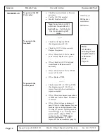
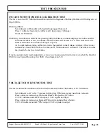
INCLINE POTENTIOMETER CALIBRATION TEST
This test can correct E1: Minimum conditions and aid in diagnosis of incline problems with finding zero or
target incline.
SS100 and SS90
Set voltmeter to Ohms (
Ω
) with treadmill unplugged from wall
Place 1 voltmeter lead on pin 3 (Blue) and 1 lead on pin 2 (Orange)
Check for 800 Ohms
SS90 Only: In calibration mode before pressing Start, the Distance window displays the incline number.
With the treadmill at zero, the number should be between 160 and 180. 0 often indicates a wire
harness misconnection or failure of signal to panel.
As the unit inclines during calibration, watch the numbers in the Distance window, if they do not
increase by at least 60 from the zero value, an E1: Minimum error will result. Then the zero value
may need to be rest to a lower value.
If incline potentiometer needs adjustment, remove swivel opines and twist incline motor shaft by hand for
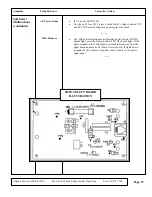
SS100 or use Up and Down keys for SS90. (See diagram on T-6)
VOLTAGE TO INCLINE MOTOR TEST
This test is utilized in conditions of No Incline Movement, Incline Fluctuation, or E1: Minimum.
Set voltmeter to AC volts. To access incline plug, PWM screws may need to be removed.
Place voltmeter leads across White and Black while pushing UP button
10 VAC indicates normal PWM output, 0 VAC signals no output
Place voltmeter leads across Red and White while pushing Down button
110 VAC indicates normal PWM output, 0 VAC signals no output
Page 23
Summary of Contents for 350 Black
Page 20: ...Page 18...
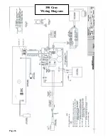
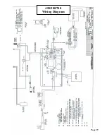
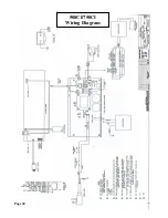
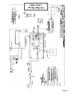
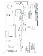
Page 28: ...Page 26 350 Gray Wiring Diagram...
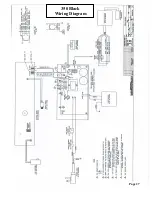
Page 29: ...Page 27 350 Black Wiring Diagram...
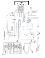
Page 30: ...Page 28 400 Wiring Diagram...
Page 31: ...Page 29 450 500 700 Wiring Diagram...
Page 32: ...Page 30 500CI 750CI Wiring Diagram...
Page 33: ...Page 31 500CI 750CI Wiring Diagram...
Page 34: ...Page 32 750 Wiring Diagram...

