background image

CHAPTER 7: ADDITIONAL INFORMATION 


Truefitness.com / 800.426.6570 / 636.272.7100  

94 

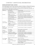
TROUBLESHOOTING GUIDE: 

This troubleshooting guide is intended to assist in diagnostics only and is not all inclusive. Technical specifications, error 

codes and programming are subject to change without notice. TRUE accepts no liability for any damage or loss suffered by 

persons whom rely wholly or in part on any description or statement contained within this manual. Please visit 

www.truefitness.com to obtain the most recent version of all manuals and contact the TRUE Service Department at 800-

883-8783 for assistance with troubleshooting and diagnostics.


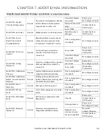
Malfunction 

Possible Cause 

Corrective Action 

No Power 

Unit is turned off 

Verify the On/Off switch is at the ON position 

Damaged power cord 

Replace power cord 

Power cord not fully seated in 

socket 

Inspect power connection at the unit and outlet 

No power at wall outlet 

Use a voltmeter to verify power at wall outlet 

Optional ERP board damaged 

Contact True Fitness Customer Service Department 

Battery is discharged 

Charge the battery overnight with optional power supply  

Motor control board damaged 

Contact True Fitness Customer Service Department 

Unit resets or 

pauses randomly 

Damaged power cord 

Replace power cord 

Power cord not fully seated in 

socket 

Inspect power connection at the unit and outlet 

Insufficient power 

Verify output voltage from 20A outlet with a voltmeter 

Error code is displayed on 

console 

Contact True Fitness Customer Service Department 

Speed sensor out of alignment 

Contact True Fitness Customer Service Department 

Pinched or loose main 

communication cable 

Contact True Fitness Customer Service Department 

Resistance 

hesitates or slips 

when pedaling  

Loose belt tension 

Contact True Fitness Customer Service Department 

Rubbing or 

knocking sound 

from unit when in 

operation 

Uneven floor 

Adjust equipment with leveling feet.   

Loose hardware 

See Chapter 5: inspections 

Loose Pedal 

See Chapter 5: inspections 

Bearings may be damaged 

Contact True Fitness Customer Service Department 

Brake assembly may be damaged  Contact True Fitness Customer Service Department 
Drive belt may be misaligned 

Contact True Fitness Customer Service Department 

No TV displayed 

or low quality 

Low or bad video signal  

Contact video provider 
NTCS dBmV 0 through15.6                                                    

ATCS/QAM dBmV-10 through 15.5 

Loose F type connecter (coaxial 

cable) 

inspect all connections 

Encrypted video 

Obtain set top box from video provider 

Channels or format type not 

correct  

Verify video type with provider; analog (NTCS), digital air 

(ATCS), digital cable (QAM) 
Rescan TV channels 

Tuner Invalid  

Contact True Fitness Customer Service Department 

Summary of Contents for CS400

Page 1: ... Assembly Guide Warranty Card Included Revision 122613 CS400 UPRIGHT BIKE OWNER S MANUAL ...

Page 2: ... library 29 international manuals ھﺎم ﺟﻣﯾﻊ اﻟﻣﻧﺗﺟﺎت ھﻲ اﻟﻣﻌروﺿﺔ اﻟﻧﻣوذج ﺗﺧﺗﻠف ﻗد اﻟﻔﻌﻠﻲ اﻟﻣﻧﺗﺞ ﺗﺳﻠﯾﻣﮭﺎ و اﻟﻣﻧﺗﺞ ﻣواﺻﻔﺎت واﻟﺑراﻣﺞ اﻟﻣﯾزات ﻟﻠﺗﻐﯾﯾر ﻗﺎﺑﻠﺔ إﺷﻌﺎر دون ﻟ ﯾﺻل ﻣﺎ ﻣﻌظم اﻵن ﺣﺗﻰ اﻟﻣﺎﻟك دﻟﯾل زﯾﺎرة ﯾرﺟﻰ www truefitness com ﻟﻠﻣﺳﺗﻧدات ﻟﻐﺎت ﻓﻲ ﯾرﺟﻰ إﺿﺎﻓﯾﺔ زﯾﺎرة www truefitness com document library 29 international manuals WICHTIG Alle hier gezeigten Produkte sind Prototypen Das tatsächliche Produk...

Page 3: ...the TRUE experience Innovation across the full product line has made TRUE successful and is a trademark of the TRUE heritage TRUE s patented Heart Rate Control technology is just one of the remarkable ways we deliver simple and superior performance every user can enjoy and most importantly use to achieve personal health and fitness goals TRUE strives to perfect biomechanically correct and orthoped...

Page 4: ...d Overview 39 Touchscreen Introduction 41 Touchscreen Navigation 41 iPod Integration 47 TV Controls 48 Virtual Active 49 Netpulse 49 Advanced Console Functions 50 Chapter 4B Escalate9 Operation Escalate 9 Overview 65 Console Navigation 67 Advanced Console Functions 73 Chapter 4C Emerge Operation Emerge Overview 82 Console Navigation 84 Advanced Console Functions 86 Chapter 5 Care Maintenance Care ...

Page 5: ...pting any maintenance activity Do not handle the plug with wet hands WARNING To reduce the risk of burns fire electric shock or injury it is imperative to connect each product to a properly grounded 110V electrical outlet A risk of electrical shock may result from improper connection of the equipment s grounding conductor Check with a qualified electrician if you are unsure about proper grounding ...

Page 6: ...n this product so the power cord plug is accessible to the user Keep the power cord away from heated surfaces Do not pull the equipment by the power cord or use the cord as a handle Do not run the power cord along the side or under the Bike If the bike power supply cord is damaged it must be replaced by the manufacturer an authorized service agent or a similarly qualified person to avoid a hazard ...

Page 7: ...ught between moving parts by making sure that they are out of reach of the bike while it is in motion Allow only one person at a time on the bike while it s operating It is the sole responsibility of the owner operator to ensure regular and scheduled maintenance is performed This appliance can be used by children aged from 8 years and above and persons with reduced physical sensory or mental capab...

Page 8: ... provided with the product if it will not fit the outlet have a proper outlet installed by a qualified electrician Do not remove any covers or you may risk injury due to electric shock The 120 V model is for use on a nominal 120 V circuit and has a grounding plug that looks like the plug illustrated in figure A Make sure the product is connected to an outlet having the same configuration as the pl...

Page 9: ...CHAPTER 1 SAFETY INSTRUCTIONS Truefitness com 800 426 6570 636 272 7100 5 ...

Page 10: ...y be worn damaged or missing To replace any worn or missing warning decals contact TRUE FITNESS by one of the following www truefitness com or contact customer service at 800 883 8783 COMPLIANCES This equipment complies with all applicable codes and regulations For a complete list of compliances please visit www truefitness com ...

Page 11: ...ling clothing while using bike Care should be used when mounting or dismounting bike Disconnect all power if applicable before servicing bike Do not exceed maximum user weight of 400 lbs Keep children and animals away Use caution when moving and assembling bike All exercise equipment is potentially hazardous If attention is not paid to the conditions of equipment usage death or serious injury coul...

Page 12: ...NS Truefitness com 800 426 6570 636 272 7100 8 PRE ASSEMBLY CHECK LIST CONTINUED Provided Hardware STEP 1 2 FRONT REAR STABILIZER BARS STEP 5 FRONT MAST STEP 6 MAST BOOT STEP 11 STORAGE TRAY STEP 8 HANDLEBAR STEP 12 CONSOLE COVERS ...

Page 13: ...ssembling bike It is recommended that at least two people unpack and assemble bike Remove all bike components from packaging For each step use hardware in the corresponding bag Sub Assembly Identification Use the image below as a reference for where the provided sub assemblies will be located in the complete bike assembly ...

Page 14: ...zer installation steps For each screw install through split washer then flat washer Insert Rear Stabilizer into the metal bracket Install each screw through the bottom of the metal bracket then through the Rear Stabilizer Tighten using the provided hex wrench Rotate the frame backwards on the Rear Stabilizer At least one person should hold the frame while another person completes the remaining Fro...

Page 15: ...o the Seat Post Mounting Plate the threaded rods on the bottom of the Seat Saddle will align with the 3 openings on the Seat Post Mounting Plate For each threaded rod install flat washer followed by nut Tighten using the provided wrench Preparation for Step 4 Install the Mast Boot component including rubber gasket onto the Front Mast tube Verify that the Mast Boot is installed in the correct orien...

Page 16: ... 272 7100 12 BIKE ASSEMBLY STEPS continued Preparation for Step 4 continued IMPORTANT Prior to Routing the Front Mast Cables it is very important that the following cable connection is confirmed If this connection is not made the Console will not be able to turn on ...

Page 17: ...on on page 23 prior to completing this step if this unit will be paired with a touchscreen or 15 TFT console Pull tie provided with the front mast see image above NOTE This connector is only used for the touchscreen console installation If installing a touchscreen console please refer to Power Supply Installation Step A before proceeding with Front Mast Cable Routing Step 4 ...

Page 18: ...ny wires between the Front Mast and the frame Verify that the Front Mast is in the correct orientation reference the provided image left Secure the Front Mast to the bike frame by tightening all 6 screws with the provided hex wrench Verify that the Front Mast is secured tightly to the bike frame tighten screws if necessary Step 6 Mast Boot Pull down the Mast Boot Attach the Mast Boot to the plasti...

Page 19: ...ttention that the Handlebar Cables are pulled all the way through the Front Mast so that no cables become pinched between the Handlebar U bracket and Front Mast For each screw install through split washer then flat washer Secure the Handlebar to the Front Mast by tightening all 3 screws with the provided hex wrench Verify that the Handlebar is secured tightly to the Front Mast tighten screws if ne...

Page 20: ... Mounting Plate Attach the Console to the Mounting Plate by tightening all 4 screw with a Phillips head screwdriver not provided At least one person should hold the Console while the remaining Console mounting steps are completed Step 10 Grounding wire Connections Remove Electronics Board ground wire screw image left Re attach both the Electronics Board ground wire and the Console ground wire to t...

Page 21: ...onics Board Cable Connections HANDLEBAR CABLE CONNECTIONS Telemetry HR o 3 pin connector Right Thumb Switch o 6 pin connector o not used on CS400 CHR_ L CHR_ R o Both 3 pin connector o It is acceptable to install either cable connector into either Electronics Board CHR location FRONT MAST CABLE CONNECTION 20 pin Connector ...

Page 22: ...FT console For other consoles proceed to Step 10B 15 TFT Console 10 Touchscreen Console NOTE Ethernet Coaxial cable connections are not available on the Orange LED or 9 TFT Consoles The Ethernet Port on the 15 TFT Console is non functioning All Ground Wires Must be connected Power Cable 2 Pin Network Cable Coaxial Cable Data Cable 50 Pin Ground Wire Remove Warning Label to access data port Do Not ...

Page 23: ...oceed to Step 10B 15 TFT Console 10 Touchscreen Console NOTE Ethernet Coaxial cable connections are not available on the Orange LED or 9 TFT Consoles The Ethernet Port on the 15 TFT Console is non functioning All Ground Wires Must be connected This connector is only used with an Optional TV Mount Ensure the Ground Cable is attached by the Ground Screw Location Varies By Model Tuck excess Cable len...

Page 24: ... installing a 9 TFT console or an LED console For other consoles return to Step 10A 9 TFT Console Orange LED Console Connect Data Cable 50 pin Both 9 TFT Orange LED Consoles Connect Power Cable 2 pin 9 TFT Console Orange LED Console NOTE Ethernet Coaxial cable connections are not available on the Orange LED or 9 TFT Consoles All Ground Wires Must be connected ...

Page 25: ...Covers For all hardware tighten using a Phillips head screwdriver not provided Attach the Front Cover P13 to the Front Mast tube using a single X06 fastener pay special attention to make sure the Front Cover P13 aligns with the Storage Tray plastic around the Handlebar Align the Back Cover P22 with the Front Cover P13 such that the plastic seams fit together Attach the Back Cover P22 to the Consol...

Page 26: ...tep 13 Pedals Align the Left Pedal with the Left Crank and the Right Pedal with the Right Crank pedals should be clearly labeled on the Pedal Strap Secure each pedal to the appropriate crank using the provided wrench NOTE The left pedal is reverse threaded turn counter clockwise to tighten Step 14 Cup Holders ...

Page 27: ...TRUCTIONS Truefitness com 800 426 6570 636 272 7100 23 BIKE ASSEMBLY STEPS continued Unit Leveling if necessary Turn feet 4x located on the front and rear stabilizer to adjust the levelness of the unit Final Unit Connections ...

Page 28: ... ASSEMBLY INSTRUCTIONS Truefitness com 800 426 6570 636 272 7100 24 BIKE ASSEMBLY STEPS continued Optional Touchscreen Console 15 TFT Console Connections Optional 9 TFT Console and Orange LED Console Connections ...

Page 29: ... 800 426 6570 636 272 7100 25 BIKE ASSEMBLY STEPS continued IMPORTANT The following steps are only required if this unit will be paired with a touchscreen console or 15 TFT Console Power Supply Installation Step A cable routing Reconnect Disconnect ...

Page 30: ...he Access Plastic fasteners quantity 3 with a Phillips head screwdriver not provided Remove the Access Plastic Power Supply Installation Step C remove wire tie Remove the wire tie shown in the provided image left This will release the Power Supply Input Plug Use caution not to drop the loose wire tie into the machine after it has been removed Remove wire tie Input Plug ...

Page 31: ...nued Power Supply Installation Step D input plug connection Connect the Input Plug to the Power Supply If necessary the Mast Boot installation step 6 can be removed to allow more access to the Power Supply cable connections Power Supply Installation Step D output plug connection Raise Mast Boot Optional ...

Page 32: ...hould also secure the extra Power Supply cables Verify that there is no interference between the wire ties or cables and the moving brake flywheel To install each wire tie first wrap underneath the square frame tube behind the Power Supply Then slide the wire tie forward into position Power Supply Installation Step E secure the power supply Insert the Access Plastic Re install the Access Plastic f...

Page 33: ...ERVIEW Truefitness com 800 426 6570 636 272 7100 29 BIKE OVERVIEW Console Assembly Contact Heart Rate Pads Leveling Feet Seat Adjustment Handle Pedals Bottle Holder Battery Charge Port Coaxial Port Ethernet Port Power Cord ...

Page 34: ...Adjustment Handle Used to adjust the vertical position of the seat to a comfortable position for the user Bottle Holder Holds an average size drink bottle for convenient use during a workout Pedals Moving part of the bike that provides resistance to the lower body during a workout Leveling Feet An adjustable system used to aid in the leveling the bike Battery Charge Port An external port used to c...

Page 35: ...prior to the workout if desired A Note on Chest Strap Heart Rate Monitoring The chest strap produces a radio signal that the bike reads and registers as the user s heart rate The accuracy of a reading may be affected when outside interference is present Contact Heart Rate CHR The CHR system will let the user monitor their heart rate without wearing a chest strap When using the CHR system users sho...

Page 36: ... they feel to ensure safety and comfort After users have spent some time learning how their heart responds to different workout intensity levels they will have a better understanding of how to use the bike to reach their target heart rate Warm Up At the beginning of an HRC workout the bike is in full Manual Control mode Users should gradually increase the workout intensity to slowly raise their he...

Page 37: ...ut continues until it is ended by the user Manual Users enter their weight workout time or distance The user controls the workout intensity throughout the workout Hill Intervals Hill intervals are in 2 minute segments with increased WORKLOAD to simulate hills Rolling Hills A series of gradual increasing and decreasing WORKLOAD changes that simulate rolling hills Users can adjust their LEVEL at any...

Page 38: ...o Challenge WORKLOAD and suggested PACE RPM increase to a maximum at the mid point of the workout then decrease to the finish Pace Intervals This workout suggests PACE RPM intervals in 1 minute segments The PACE SETTER shows the target pace along with the user s actual pace RPM throughout the workout Pace Ramp This workout suggests PACE RPM increases to a maximum at the mid point of the workout an...

Page 39: ...LOAD to maintain the user s HR within a few beats of their target HRC Weight Loss Based on age this is a heart rate controlled workout at 65 of the user s maximum heart rate This creates efficient fat burning without overtraining The workout begins in MANUAL control Users should gradually increase WORKLOAD until their heart rate is within 10 bpm of their target At this point the machine takes cont...

Page 40: ...ir target At this point the machine takes control to keep the user s HR within a few beats of their target HRC Distance Workouts 4 popular fixed distance workouts 5K 10K 2 mile and 4 mile that put the machine in control of maintaining the user s target heart rate The workout begins in MANUAL control Users should gradually increase WORKLOAD until their heart rate is within 10 bpm of their target At...

Page 41: ...outh Tyrol Gampenjoch Bolzano South Tyrol Chicago Run Explore the tall buildings and wide public parks of this Midwestern metropolis From the sculpture gardens of Millennium Park to the shores of Lake Michigan to the shops that line the Magnificent Mile the Windy City boasts spectacular sights The guided workout is speed focused and includes two challenging sprints Destinations Include Grant Park ...

Page 42: ...osemite National Park and General Sherman the world s largest tree The guided workout starts with a challenging climb to the top of Morro Rock before relaxing into a moderately difficult finish Destinations Include Sequoia National Park California Yosemite National Park California Sequoia National Forest California Trinity Mountains Hike The northwestern corner of California is home to the Shasta ...

Page 43: ...CHAPTER 4A TRANSCEND OPERATION Truefitness com 800 426 6570 636 272 7100 39 TRANSCEND OVERVIEW Touchscreen Display Cooling Fan Headphone Jack USB Jack 30 pin iPod Connector Reading Rack Warning Decal ...

Page 44: ...phone Jack Standard 3 5mm audio jack used to connect headphones to the console during media playback USB Jack Allows users to export workout data to an external USB drive or update the console software Reading Rack This ledge on the console can be used to hold a book magazine e reader or tablet computer during a workout Cooling Fan Integrated fan that delivers a cooling flow of air during a workou...

Page 45: ...se of this capacitive touchscreens are highly responsive and can be activated with very light touches of the user s finger TOUCHSCREEN NAVIGATION TRUE recommends that users familiarize themselves with the different screens to ensure that they are safely taking advantage of all of the features that this equipment has to offer Icon Character Map This console uses several icons to provide users with ...

Page 46: ...ttings The workout continues until it is ended by the user B Safety Instructions Displays a list of safety instructions for users to review prior to beginning a workout C Workout Finder Displays preset workouts categorized by goal focused categories D Language Options Allows users to choose between 12 language options E iPod Displays the iPod interface without starting a workout F TV Displays TV i...

Page 47: ...n button A or swipe through categories in the category preview window B Workouts can also be viewed in an uncategorized list by touching Show All Workouts button C Workout Data Entry Screens Workout data entry screens allow the user to input their personal information or workout goals prior to beginning a preset workout To set a value touch the heading A of the value and adjust the slider B to the...

Page 48: ... A1 B Workload Level Displays the current Workload level C Heart Rate Information When the user is wearing a heart rate chest strap or utilizing the contact heart rate system their heart rate will be displayed in beats per minute bpm and in the graphic meter The graphic meter is based on age and will gauge the user s approximate heart rate within 3 target levels Weight Loss Aerobic or Performance ...

Page 49: ...a more realistic biking experience D Cool Down This button is displayed by touching the Show Hide Tools button B and allows the user to end their current workout with a two minute low intensity cool down period When Cool Down is activated the unit is in manual mode and the user directly controls all settings E Fan On Off This button is displayed by touching the Show Hide Tools button B and turns t...

Page 50: ...e main display window B to scroll through the available screens Workout Summary Screen At the end of a workout the Summary Screen will display an overview of the workout data The workout data can be exported to another device by inserting a USB drive into the console s USB port and touching the Save button A By default the Workout Summary Screen will be displayed for one minute If the user require...

Page 51: ... 30 pin connector located on the front of the console Once connected the user can control the functions of their iPod through the user friendly touchscreen interface A Volume Controls Increases Decreases or Mutes the audio volume from the iPod B Navigation Buttons Allows the user to Play Pause or Skip media and navigate the iPod menu C Menu Button When pressed the menu button will return to the pr...

Page 52: ...user to monitor their workout while enjoying their favorite shows A Volume Controls Increases Decreases or Mutes the audio volume from the TV program B Closed Captioning Toggles the closed captioning on or off This button will only be visible when the program displayed supports closed captioning C Channel Keypad Displays the channels that are currently available for viewing D Screen Toggle Allows ...

Page 53: ... Screen Toggle Button B Audio Volume C can also be adjusted NETPULSE Netpulse is a digital fitness solution that enables personalized goal setting activity based social feeds workout tracking data management and on demand content Netpulse works with 3rd party tracking apps and devices along with a mobile app and web portal for capturing all of the user s data Users that wish to utilize Netpulse co...

Page 54: ...ering Service Mode can be completed by pressing and holding the TRUE logo A in the upper left corner of the home screen When the word TRUE B begins to flash release the logo and press and hold the lower right corner of the screen C Main Menu After successfully entering service mode the screen below will be displayed From this menu users can access all of the service mode features by navigating thr...

Page 55: ...onfigured to B Product Type Specifies if the console is configured for a treadmill bike or elliptical C Serial Number The serial number of the console not the base unit D Software Version The current version of software that is installed on the console E Firmware Version The current version of firmware that is installed on the console F Bootloader Version The current bootloader version that is ins...

Page 56: ...unctions of the unit Setup Menu Product Setup The Product Setup allows users to change the console configuration to match the unit on which it is installed To change the console configuration From the Main Menu touch the Setup button From the Setup Menu Press Product Setup A Touch the correct model number to select it B Touch the Save key to save the configuration C A B C Sub Categories can be acc...

Page 57: ...ortant for troubleshooting purposes when viewing the system s error log Setting the Clock From the Main Menu press the Setup button From the Setup Menu press the Clock Button A Touch the arrows B to adjust the date and time and use the slider button C to select AM or PM Once the correct time and date are entered touch the Next key D Use the slider E or swipe through the list of time zones until th...

Page 58: ...the Save button C to save the images to the console Additional Screen Saver Options Custom Screen Saver images can be deleted by touching the clear button D The amount of time the console must be idle before the screen saver engages can be adjusted by using the Screen Saver Time Slider E The Sleep timer is a function that will turn off the console s back light after a period of time to save energy...

Page 59: ...ll need to be placed on a USB drive in a folder named facility case sensitive Importing Screen Saver Images Touch the Facility Images button A Insert the USB drive that contains the JPG images into the console s USB port Verify the images in the preview window B Touch the Save button C to save the images to the console Facility images can be deleted by touching the clear button D Once loaded corre...

Page 60: ...V Setup Steps From the Main Menu press the Setup button From the Setup Menu press the TV Setup button A Touch the Channel Scan button B to setup the TV signal Use the Slider button C to select the source of signal is being used Antenna or Cable Select what type of signal is being used by touching either Analog or Digital D When analog is selected the user will need to choose the analog standard NT...

Page 61: ... add a network logo J to a channel Press the TV icon K next to the channel number and select the appropriate logo from the pop up list provided TV Configurations can be exported to USB as a backup or to use for setting up multiple consoles Once the Setup is complete insert a USB stick into the console s USB port and touch the Export to USB button L Once all the settings are completed simply press ...

Page 62: ...t To Configure Netpulse From the Main Menu press the Setup button From the Setup Menu press the Network Setup button B Touch the Netpulse Enabled Slider button C to enable it Touch the Configure Netpulse Button D On the screen that follows touch the Test Network button Once the screen displays the message All network tests passed touch the Install button The screen will then display the message In...

Page 63: ...SB devices C Contact Heart Rate Has Priority When enabled the console will attempt to read heart rate data from the contact heart rate grips before reading data from a wireless chest strap When this option is turned off telemetry heart rate will take priority D LCD Brightness Use the slider to adjust the brightness of the touchscreen display E System Sound Volume Use the slider to adjust the volum...

Page 64: ...nual workouts or distance workouts C Workout Setup Timeout Choose how long the workout data entry screen will remain on the display without any user interaction By choosing the off setting the data entry screen will be displayed until closed by a user D Workout Summary Timeout Determines the amount of time the Workout Summary Screen will remain on the display By choosing the Off setting the summar...

Page 65: ...istance C is the total distance in miles that the unit has traveled Distance D is the amount of distance the unit has traveled since the last time the Clear Mileage button E was pressed The Distance Clear Mileage feature is helpful for tracking mileage in a preventive maintenance schedule Touching the Program Usage button C will provide a list of programs that have been used on the unit and how ma...

Page 66: ...erference from another source This unit is designed to receive 5 khz non coded transmissions only C Keypress When a quick access key is pressed on the unit NONE will change to indicate which key is being pressed In the event of a stuck key the key that is being engaged will display D Fan Speed Control Using the slider allows users to test the fan independent of a program E Pedal RPM While a user i...

Page 67: ...mmended Diagnostics Menu Software Update TRUE may periodically release software updates to ensure users enjoy the best workout experience available To update the console software load the deb file on a blank USB drive as shown and follow the steps on the next page WARNING To avoid errors and console damage all files or documents on the USB stick other than the TRUE software update must be placed i...

Page 68: ...Touching the Touchscreen key A will open the touchscreen calibration tool On the first screen displayed users can touch anywhere in the white area B and a small red box C will appear to verify screen function Touching the Calibrate button D will begin a touchscreen calibration During this process targets will appear on the screen and the user must press and hold each target until it turns red to c...

Page 69: ...ERATION Truefitness com 800 426 6570 636 272 7100 65 ESCALATE9 OVERVIEW LCD Display Workload Keys Start Selection Buttons Selection Buttons Stop Reading Rack Headphone Jack iPod Connector Warning Decal USB Port Numeric Keypad ...

Page 70: ... used to hold a book magazine e reader or tablet computer during a workout USB Port Allows users to export workout data to an external USB drive or update the console software Numeric Keypad A small panel of keys on the console that allow the user to quickly enter numeric data Headphone Jack Standard 3 5mm audio jack used to connect headphones to the console during media playback iPod Connector St...

Page 71: ...ress From this screen the user is able to select from various options to begin a workout A Workout Finder Displays preset workouts categorized by goal focused categories B Quick Start Starts a Quick Start workout in which the user controls all settings until the workout is ended by pressing Stop or Cool Down C Language Options Allows users to choose between 12 language options B B C ...

Page 72: ...ress the Next Selection Button C Press and hold the Next Selection Button to return to the previous screen Workout Data Entry Screens These screens allow users to input their personal information or workout goals prior to beginning a workout To set a value press the Selection Button for the value you wish to change A and use the Workload Keys B to adjust the value to the desired setting Users may ...

Page 73: ...ose custom data points to be seen in this display See Workout Data Screen Controls E Show Tools section below B Time Displays the time elapsed for the current workout C Workload Shows the current workload level D Pace Displays the current pace of a workout E Custom Data Display 2 By Default this display will show the calorie count for the current workout Users can also choose custom data points to...

Page 74: ... for the control they wish to use A Change View Switches between the available Workout Data Screens B Cool Down Pressing this button allows the user to end their current workout with a two minute low intensity cool down period When Cool Down is activated the unit is in manual mode and the user directly controls all settings C HRC Cruise Engages Heart Rate Control to allow the equipment to maintain...

Page 75: ...olume A and channel adjustments B E Show Tools Pressing the Show Tools Selection Button A will display various options Pressing the Change Data Selection Button C will toggle the data points in Custom Data Display 1 1 between distance and watts The data points in Custom Data display 2 2 will toggle between calories and METs Pressing the Scroll Data Selection button B will allow the Custom Data Dis...

Page 76: ...alculates speed A for a more realistic biking experience Using the Workload Keys B will change the simulated gears C Workout Summary Screen At the end of a workout the Summary Screen will display an overview of the workout data The workout data can be exported to another device by inserting a USB drive into the console s USB port and pressing the Save Selection Button A or to return to the home sc...

Page 77: ...kout Finder icon blinks release and hold the Workout Finder selection button C until the service screen displays Service Menu The first screen displayed after entering service mode is the Service Menu From this menu technicians can access all of the service mode features by selecting different categories To select a category use the scroll selection buttons A to highlight a category B Once a categ...

Page 78: ...changed in this screen A Product Model The model number that the console is currently configured to B Software Version The current version of software that is installed on the console C Units Displays the units the console is currently using as default U S or Metric D Max Watts Displays the maximum power the unit is capable of producing E Max User Weight The amount of user weight that the unit can...

Page 79: ...g the enter selection button C to confirm the selection Utilities Menu Product Setup The product setup screen allows for adjustments to be made to the model configuration TRUE s recommendation is to only use the Setup Wizard to adjust these attributes After pressing the Setup Wizard Selection Button A simply follow the on screen instructions to complete the setup procedure WARNING Misconfiguration...

Page 80: ...o the software update screen and insert the USB drive into the console s USB port When the console recognizes the software it will show a message that reads Drive found and ready Press Update to begin Warning Improper use can render this machine inoperable To complete the update press the update selection button A WARNING To avoid errors and console damage all files or documents on the USB stick o...

Page 81: ... audio source is connected to the wireless transmitter and both the source and the transmitter are powered on 1 Use the Scroll Selection Buttons A to highlight the desired transmitter series from the list BV TV SERIES 1 9 B Broadcast Vision Transmitters BV TV SERIES 2 Mye and Fantaay Transmitters BV TV SERIES 4 Cardio Theater LCS Transmitters BV TV SERIES 8 Cardio Theater xTV Transmitters BV TV SE...

Page 82: ... a channel push the Save Selection Button E to save the channel NOTE The order in which the channels are saved determines the order that they are displayed in standard user mode 6 Repeat steps 4 and 5 for each additional audio source 7 If a channel needs to be removed use the Channel Selection Buttons D to scroll to the channel and press the Unsave Selection button F 8 Once all desired channels ar...

Page 83: ...e back selection button D and the changes will be automatically saved Language Select a default Language for the unit All settings and workout data will be displayed in that language Units Choose how the workout data is displayed by default Save Workout Turns the saved workout feature on or off Heart Rate Priority Determines the order in which the unit reads heart rate data Cooldown Adjusts the le...

Page 84: ... the off setting the data entry screen will be displayed until closed by a user Summary Timeout Determines the amount of time the Workout Summary Screen will remain on the display By choosing the Off setting the summary will be displayed until ended by a user Pause Time This setting will limit the amount of time that a workout can be paused before it automatically ends By choosing the Off option t...

Page 85: ... a service professional This console is capable of storing the ten most recent errors The error log can be cleared by pressing the enter selection button A but it is not recommended Statistics An overview that includes distance time manual program count preset program count and apple device connections These statistics can be exported to a connected USB drive by using the scroll selection buttons ...

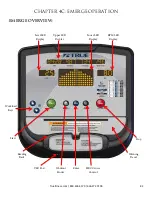
Page 86: ...ruefitness com 800 426 6570 636 272 7100 82 EMERGE OVERVIEW Upper LED Display Lower LED Display Workload Keys Start Reading Rack USB Port Workout Finder Enter HRC Cruise Control Warning Decal Stop RPM LED Display Level LED Display ...

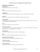
Page 87: ...er must press Enter to input their data and start to begin the workout Enter Press this key to confirm a selection in a preset workout HRC Cruise Control Engages Heart Rate Control to allow the equipment to maintain the user s current heart rate through automatic workload adjustments when the user is utilizing heart rate monitoring Warning Decal Important safety information for users to review pri...

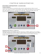
Page 88: ...on C To begin a Target HRC Workout press the HRC Cruise Control button D followed by the Enter button C Workout Data Entry Before beginning a preset workout the console will ask the user for information in order to give more accurate workout data To adjust the Data Value A use the Up and Down Workload Keys B Once the desired value is displayed press Enter C to move to the next Data Value Once all ...

Page 89: ...erage Heart Rate Max Heart Rate Average RPM Max RPM Distance and Calories To Clear the Summary and return to the home screen press the Stop button A Exporting Workout Data to a USB Drive The Emerge Console gives users the ability to export their workout data to a USB drive When this option is enabled the screen below will appear before the Workout Summary To export the data insert a USB drive into...

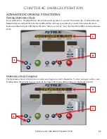
Page 90: ...d the Enter Button B until the unit beeps again about 3 seconds Then release the Enter button and when the Upper LED Display C reads Maintenance Mode press the Enter Button B to enter maintenance mode Maintenance Mode Navigation The Maintenance Mode is divided into two categories Diagnostics and Configuration To select a category use the and Workload Keys A until the category is listed in the Uppe...

Page 91: ... to change the options within the setting After changing any setting the Start Button D MUST be pressed to save the changes if the start button is not pressed to save the changes the setting will revert to the default value The Stop Button E is used as a back button in Maintenance Mode and will take the user back one screen each time it is pressed To exit the maintenance mode press the Stop Button...

Page 92: ... that all workouts can last does not apply to quickstart manual or distance workouts Power Enables the use of an optional power supply Pause Time This setting will limit the amount of time that a workout can be paused before it automatically ends By choosing the Off option the unit will remain paused until the user resumes or ends the workout Cooldown Adjusts the length of the cooldown time at the...

Page 93: ... is being engaged will display HR Test Telemetry Use a wireless heart rate strap or simulator to test if the unit is receiving wireless heart rate data If there is a reading displayed without the use of a heart rate strap or simulator there is outside interference from another source Contact Ensures the unit is receiving the data by displaying the user s heart rate when the contact heart rate pads...

Page 94: ...that the bike needs service To order parts or to contact a TRUE Authorized Service representative please visit www truefitness com CLEANING THE EQUIPMENT After Each Use Use GymWipes Antibacterial wipes or spray a solution of 30 parts water to 1 part mild detergent to dampen a soft cloth and wipe all exposed surfaces Use a LCD screen cleaner or spray a solution of 1 part 91 isopropyl alcohol and 1 ...

Page 95: ...t all components for abnormal or premature wear Inspect and lubricate pedal threads on bike to prevent corrosion CAUTION Use only TRUE Fitness certified service providers LONG TERM STORAGE When the bike is not in use for any length of time turn it off Make sure that the power cord is unplugged from the power source and is positioned so that it will not become damaged or interfere with people or ot...

Page 96: ...ntact information for the closest dealer You may also contact TRUE Fitness customer support team by calling 800 883 8783 or e mailing us at service truefitness com Monday Friday during normal business hours TRUE FITNESS SERVICE DEPARTMENT 865 HOFF ROAD ST LOUIS MO 63366 1 800 883 8783 HOURS OF OPERATION 8 30 A M 5 00 P M CST E MAIL service truefitness com CONTACTING SALES Interested in TRUE Produc...

Page 97: ...e not sure if the actual product is damaged or not You must sign the bill of lading as damaged when accepting the shipment Once you have opened the box and you have determined something is indeed damaged please gather the serial number model number description and photos of damages Please make sure the photos include the damaged product as well as the damaged box the product arrived in Contact the...

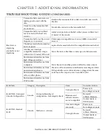
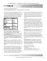
Page 98: ...ed power cord Replace power cord Power cord not fully seated in socket Inspect power connection at the unit and outlet Insufficient power Verify output voltage from 20A outlet with a voltmeter Error code is displayed on console Contact True Fitness Customer Service Department Speed sensor out of alignment Contact True Fitness Customer Service Department Pinched or loose main communication cable Co...
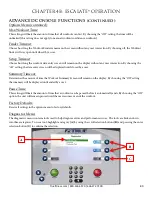
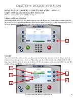
Page 99: ...f the unit Move the units so that there is more space in between units Environmental interference from high voltage power lines Move the unit to another position within the room or move the cause of the interference until heart rate reading are stable If the probable source of interference is plugged into the same outlet move the suspect source to another outlet Environmental interference from com...

Page 100: ...onfigured for a product different than that to which it is connected Console Configure incorrectly Power cycle Re configure console Loose Cable Check cable Connections Fault CN07 Calibration Timeout Console Incline Calibration was not able to complete within allowed time Unit is configured as a treadmill Re configure console Fault CN08 Calibration Failed Lower Limit Not Reached Console During incl...

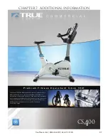
Page 101: ...art design for an overall package that is unbeatable in performance and durability With one of the lowest step up heights in the industry the CS400 offers a safe and easy entry for users of all ages and fitness levels Plus the small footprint allows you to maximize the premium space in your facility Take a new look at TRUE today Truefitness com 800 426 6570 636 272 7100 97 ...

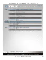
Page 102: ...APPROVALS ETL UL1647 CSA CE EN957 FCC AS4092 C TICK EXTRAS Accessories Water Bottle Holder Accessory Tray Over Molded Reading Rack Tablet Holder PHYSICAL SPECIFICATIONS Footprint 45 L x 24 W 114 cm x 61 cm Machine Weight 146 lbs 66 kg Shipping Weight 152 lbs 69 kg Maximum User Weight 400 lbs 181 kg Step Over Height 16 75 42 5 cm Portability 2 Front Transport Wheels WARRANTY Warranty Type Commercia...

Page 103: ...e abuse unauthorized modification or failure to provide reasonable and necessary maintenance TRUE Fitness shall not warrant the performance of the heart rate system on its products as the heart rate system performance varies based on user s physiology age method of use and other factors This limited warranty shall not apply to software version upgrades Cosmetics The upright bike cosmetic parts are...

Page 104: ...rein 6 This Limited Warranty shall not apply to Service calls to correct installation of the equipment or instruction to owners on how to use the equipment or any labor costs incurred beyond the applicable labor warranty period 7 This Limited Warranty is in lieu of all warranties express or implied and in lieu of all other obligations or liabilities on the part of TRUE under no circumstances shall...

Page 105: ...lity on a daily basis ___ a 25 ___ b 25 75 ___ c 76 150 ___ d 150 6 Do you plan to purchase more fitness equipment in the next 6 12 months ____ Yes ____ No 7 If you answered yes to question 6 what type do you plan to purchase ____ a Treadmill ____ b Elliptical ____ c Stationary Bike ____ d Free Weights ____ e Gym ____ f Other ______________ 8 Would you recommend TRUE to other club owners ____ Yes ...

Reviews: