background image

CHAPTER 4A: ESCALATE

9

 OPERATION 


Truefitness.com / 800.426.6570 / 636.272.7100  

36 

CONSOLE NAVIGATION (continued): 

F

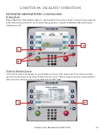
) Bike Mode: 

Engages Bike Mode, which


simulates riding a 21-speed road bike. The resistance changes to constant torque against the 

pedals and calculates speed (

A

) for a more realistic biking experience. Using the Workload Keys (

B

) will change the 

simulated gears (

C

).  


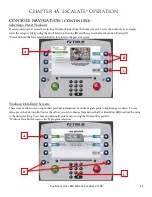
Workout Summary Screen: 

At the end of a workout the Summary Screen will display an overview of the workout data. The workout data can be 

exported to another device by inserting a USB drive into the console’s USB port and pressing the Save Selection Button 
(

A

) or to return to the home screen press the Home Selection Button (

B


Summary of Contents for ES900

Page 1: ... Assembly Guide Warranty Card Included Revision 123013 ES900 UPRIGHT BIKE OWNER S MANUAL ...

Page 2: ... library 29 international manuals ﻫﺎﻡ ﺟﻣﻳﻊ ﺍﻟﻣﻧﺗﺟﺎﺕ ﻫﻲ ﺍﻟﻣﻌﺭﻭﺿﺔ ﺍﻟﻧﻣﻭﺫﺝ ﺗﺧﺗﻠﻑ ﻗﺩ ﺍﻟﻔﻌﻠﻲ ﺍﻟﻣﻧﺗﺞ ﺗﺳﻠﻳﻣﻬﺎ ﻭ ﺍﻟﻣﻧﺗﺞ ﻣﻭﺍﺻﻔﺎﺕ ﻭﺍﻟﺑﺭﺍﻣﺞ ﺍﻟﻣﻳﺯﺍﺕ ﻟﻠﺗﻐﻳﻳﺭ ﻗﺎﺑﻠﺔ ﺇﺷﻌﺎﺭ ﺩﻭﻥ ﻟ ﻳﺻﻝ ﻣﺎ ﻣﻌﻅﻡ ﺍﻵﻥ ﺣﺗﻰ ﺍﻟﻣﺎﻟﻙ ﺩﻟﻳﻝ ﺯﻳﺎﺭﺓ ﻳﺭﺟﻰ www truefitness com ﻟﻠﻣﺳﺗﻧﺩﺍﺕ ﻟﻐﺎﺕ ﻓﻲ ﻳﺭﺟﻰ ﺇﺿﺎﻓﻳﺔ ﺯﻳﺎﺭﺓ www truefitness com document library 29 international manuals WICHTIG Alle hier gezeigten Produkte sind Prototypen Das tatsächliche Produk...

Page 3: ...the TRUE experience Innovation across the full product line has made TRUE successful and is a trademark of the TRUE heritage TRUE s patented Heart Rate Control technology is just one of the remarkable ways we deliver simple and superior performance every user can enjoy and most importantly use to achieve personal health and fitness goals TRUE strives to perfect biomechanically correct and orthoped...

Page 4: ...ing 24 Heart Rate Control 24 Program Descriptions 26 Chapter 4A Escalate9 Operation Escalate9 Overview 29 ConsoleNavigation 31 Advanced Console Functions 37 Chapter 4B Emerge Operation Emerge Overview Navigation 42 Advanced Console Functions 45 Chapter 5 Care Maintenance Care Maintenance 46 Cleaning the Equipment 46 Leveling the Unit 46 Other Scheduled Preventive Maintenance 47 Long Term Storage 4...

Page 5: ...g any maintenance activity Do not handle the plug with wet hands WARNING To reduce the risk of burns fire electric shock or injury it is imperative to connect each product to a properly grounded 110V electrical outlet A risk of electrical shock may result from improper connection of the equipment s grounding conductor Check with a qualified electrician if you are unsure about proper grounding tech...

Page 6: ...r use the cord as a handle Do not run the power cord along the side or under the Bike If the bike power supply cord is damaged it must be replaced by the manufacturer an authorized service agent or a similarly qualified person to avoid a hazard Do not use this product in areas where aerosol spray products are being used or where oxygen is being administered Such substances create the danger of com...

Page 7: ...children aged from 8 years and above and persons with reduced physical sensory or mental capabilities or lack of experience and knowledge if they have been given supervision or instruction concerning use of the appliance in a safe way and understand the hazards involved Children shall not play with the appliance Cleaning and user maintenance shall not be made by children without supervision SPACE ...

Page 8: ...is for use on a nominal 120 V circuit and has a grounding plug that looks like the plug illustrated in figure A Make sure the product is connected to an outlet having the same configuration as the plug No adaptor should be used with this product The 230 V model is for use on a circuit having a nominal rating more than 120 V and is factory equipped with a specific electric cord and has a grounding ...

Page 9: ...CHAPTER 1 SAFETY INSTRUCTIONS Truefitness com 800 426 6570 636 272 7100 5 ...

Page 10: ...y be worn damaged or missing To replace any worn or missing warning decals contact TRUE FITNESS by one of the following www truefitness com or contact customer service at 800 883 8783 COMPLIANCES This equipment complies with all applicable codes and regulations For a complete list of compliances please visit www truefitness com ...

Page 11: ...Do not wear loose or dangling clothing while using bike Care should be used when mounting or dismounting bike Disconnect all power if applicable before servicing bike Do not exceed maximum user weight of 400 lbs Keep children and animals away Use caution when moving and assembling bike All exercise equipment is potentially hazardous If attention is not paid to the conditions of equipment usage dea...

Page 12: ...NS Truefitness com 800 426 6570 636 272 7100 8 PRE ASSEMBLY CHECK LIST continued Provided Hardware STEP 1 2 FRONT REAR STABILIZER BARS STEP 5 FRONT MAST STEP 6 MAST BOOT STEP 11 STORAGE TRAY STEP 8 HANDLEBAR STEP 12 CONSOLE COVERS ...

Page 13: ...426 6570 636 272 7100 9 PRE ASSEMBLY CHECK LIST continued Additional Items Provided POLAR T34 Transmitter and Chest Strap Heart Rate Monitor Power Adaptor NOTE For the 9 TFT Console a different 12V 3A Power Adaptor is provided with the console packaging ...

Page 14: ...assembling bike It is recommended that at least two people unpack and assemble bike Remove all bike components from packaging For each step use hardware in the corresponding bag Sub Assembly Identification Use the image below as a reference for where the provided sub assemblies will be located in the complete bike assembly ...

Page 15: ...For each screw install through split washer then flat washer Insert Rear Stabilizer into the metal bracket Install each screw through the bottom of the metal bracket then through the Rear Stabilizer Tighten using the provided hex wrench Rotate the frame backwards on the Rear Stabilizer At least one person should hold the frame while another person completes the remaining Front Stabilizer installat...

Page 16: ...eat Saddle Attach the Seat Saddle to the Seat Post Adjust Seat Saddle position Tighten using the provided wrench Preparation for Step 4 Install the Mast Boot component including rubber gasket onto the Front Mast tube Verify that the Mast Boot is installed in the correct orientation reference the provided image left ...

Page 17: ...CHAPTER 2 ASSEMBLY INSTRUCTIONS Truefitness com 800 426 6570 636 272 7100 13 BIKE ASSEMBLY STEPS continued Step 4 Front Mast Cable Routing Pull tie provided with the front mast see image above ...

Page 18: ...ny wires between the Front Mast and the frame Verify that the Front Mast is in the correct orientation reference the provided image left Secure the Front Mast to the bike frame by tightening all 6 screws with the provided hex wrench Verify that the Front Mast is secured tightly to the bike frame tighten screws if necessary Step 6 Mast Boot Pull down the Mast Boot Attach the Mast Boot to the plasti...

Page 19: ...ttention that the Handlebar Cables are pulled all the way through the Front Mast so that no cables become pinched between the Handlebar U bracket and Front Mast For each screw install through split washer then flat washer Secure the Handlebar to the Front Mast by tightening all 3 screws with the provided hex wrench Verify that the Handlebar is secured tightly to the Front Mast tighten screws if ne...

Page 20: ...ewdriver not provided At least one person should hold the Console while the remaining Console mounting steps are completed Step 10 Cable Connections Locate the groud screw pre installed into the back of the Front Mast Mounting Plate Remove the ground screw with Phillips head screwdriver not provided Thread the shaft of the ground screw through the metal ring attached to the console Ground Wire Re ...

Page 21: ...Y INSTRUCTIONS Truefitness com 800 426 6570 636 272 7100 17 BIKE ASSEMBLY STEPS continued Step 10 Cable Connections continued Orange LED Console NOTE Ethernet cable connection is not available on the Orange LED Console ...

Page 22: ...SEMBLY INSTRUCTIONS Truefitness com 800 426 6570 636 272 7100 18 BIKE ASSEMBLY STEPS continued Step 10 Cable Connections continued 9 TFT Console NOTE Ethernet cable connection is not available on the 9 TFT Console ...

Page 23: ...ad screwdriver not provided Attach the Front Cover P13 to the Front Mast tube using a single X06 fastener pay special attention to make sure the Front Cover P13 aligns with the Storage Tray plastic around the Handlebar Align the Back Cover P22 with the Front Cover P13 such that the plastic seams fit together Attach the Back Cover P22 to the Console Mounting Plate using two X47 fasteners top fasten...

Page 24: ...tep 13 Pedals Align the Left Pedal with the Left Crank and the Right Pedal with the Right Crank Pedals should be clearly labeled on the Pedal Strap Secure each Pedal to the appropriate Crank using the provided wrench NOTE The Left Pedal is reverse threaded turn counter clockwise to tighten Step 14 Cup Holders ...

Page 25: ...TRUCTIONS Truefitness com 800 426 6570 636 272 7100 21 BIKE ASSEMBLY STEPS continued Unit Leveling if necessary Turn feet 4x located on the Front and Rear Stabilizer to adjust the levelness of the unit Final Unit Connections ...

Page 26: ...TER 3 PRODUCT OVERVIEW Truefitness com 800 426 6570 636 272 7100 22 BIKE OVERVIEW Console Assembly Contact Heart Rate Pads Leveling Feet Seat Adjustment Handles Pedals Bottle Holder Ethernet Port Power Cord ...

Page 27: ...to check their heart rate without wearing a wireless chest strap Seat Adjustment Handles Used to adjust the position of the seat to a comfortable position for the user Bottle Holder Holds an average size drink bottle for convenient use during a workout Pedals Moving part of the bike that provides resistance to the lower body during a workout Leveling Feet An adjustable system used to aid in the le...

Page 28: ... prior to the workout if desired A Note on Chest Strap Heart Rate Monitoring The chest strap produces a radio signal that the bike reads and registers as the user s heart rate The accuracy of a reading may be affected when outside interference is present Contact Heart Rate CHR The CHR system will let the user monitor their heart rate without wearing a chest strap When using the CHR system users sh...

Page 29: ... they feel to ensure safety and comfort After users have spent some time learning how their heart responds to different workout intensity levels they will have a better understanding of how to use the bike to reach their target heart rate Warm Up At the beginning of an HRC workout the bike is in full Manual Control mode Users should gradually increase the workout intensity to slowly raise their he...

Page 30: ...sistance changes to constant torque against the pedals and calculates speed for a more realistic biking experience Hill Intervals Hill intervals are in 2 minute segments with increased WORKLOAD to simulate hills Rolling Hills A series of gradual increasing and decreasing WORKLOAD changes that simulate rolling hills Users can adjust the WORKLOAD at any time during the workout to increase or decreas...

Page 31: ...he mid point of the workout and then decreases to the finish The PACE SETTER shows the user s target pace throughout the workout Leg Shaper A workout that suggests PACE changes to work the leg muscles with added intensity Distance Workouts Choose from four common distance workouts 5k 10k 2 mile or 4 mile Saved Workouts Access to previously saved workouts Custom Ultra If users are having trouble fi...

Page 32: ...f WORKLOAD to maintain the user s HR within a few beats of their target HRC Aerobic Based on age this is a heart rate controlled workout at 80 of the user s maximum heart rate This keeps users in the optimum aerobic training range to improve cardio fitness The workout begins in MANUAL control Users should gradually increase WORKLOAD until their heart rate is within 10 bpm of their target At this p...

Page 33: ...ness com 800 426 6570 636 272 7100 29 ESCALATE9 OVERVIEW LCD Display Decrease Workload Start Selection Buttons Selection Buttons Stop Reading Rack Headphone Jack 30 Pin iPod Connector Warning Decal USB Port Numeric Keypad Increase Workload ...

Page 34: ...d to hold a book magazine e reader or tablet computer during a workout USB Port Allows users to export workout data to an external USB drive or update the console software Numeric Keypad A small panel of keys on the console that allow the user to quickly enter numeric data Headphone Jack Standard 3 5mm audio jack used to connect headphones to the console during media playback 30 Pin iPod Connector...

Page 35: ...ole when there is no workout in progress From this screen the user is able to select from various options to begin a workout A Workout Finder Displays preset workouts categorized by goal focused categories B Quick Start Starts a Quick Start workout in which the user controls all settings until the workout is ended by pressing Stop or Cool Down A B ...

Page 36: ...ress the Next Selection Button C Press and hold the Next Selection Button to return to the previous screen Workout Data Entry Screens These screens allow users to input their personal information or workout goals prior to beginning a workout To set a value press the Selection Button for the value you wish to change A and use the Workload Keys B to adjust the value to the desired setting Users may ...

Page 37: ...ose custom data points to be seen in this display See Workout Data Screen Controls E Show Tools section below B Time Displays the time elapsed for the current workout C Workload Shows the current workload level D Pace Displays the current pace of a workout E Custom Data Display 2 By Default this display will show the calorie count for the current workout Users can also choose custom data points to...

Page 38: ... for the control they wish to use A Change View Switches between the available Workout Data Screens B Cool Down Pressing this button allows the user to end their current workout with a two minute low intensity cool down period When Cool Down is activated the unit is in manual mode and the user directly controls all settings C HRC Cruise Engages Heart Rate Control to allow the equipment to maintain...

Page 39: ...Pressing the Show Tools Selection Button A will display various options Pressing the Change Data Selection Button C will toggle the data points in Custom Data Display 1 1 between distance and watts The data points in Custom Data display 2 2 will toggle between calories and METs Pressing the Scroll Data Selection button B will allow the Custom Data Displays to automatically toggle between data poin...

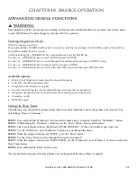
Page 40: ...lculates speed A for a more realistic biking experience Using the Workload Keys B will change the simulated gears C Workout Summary Screen At the end of a workout the Summary Screen will display an overview of the workout data The workout data can be exported to another device by inserting a USB drive into the console s USB port and pressing the Save Selection Button A or to return to the home scr...

Page 41: ... blinks release the upper right selection button and hold the Workout Finder selection button C until the service screen displays Service Menu The first screen displayed after entering service mode is the Service Menu From this menu technicians can access all of the service mode features by selecting different categories To select a category use the scroll selection buttons A to highlight a catego...

Page 42: ...een provides an overview of the unit s current settings values cannot be changed in this screen A Product Model The model number that the console is currently configured to B Software Version The current version of software that is installed on the console C Units Displays the units the console is currently using as default U S or Metric A B C ...

Page 43: ...tion Button A to set the time and date Setting Time and Date Use the Previous and Next Selection Buttons A to highlight the field to be changed Then use the adjustment selection buttons B to adjust the selected value Once all adjustments have been made press the Save Selection Button C to save the changes saving changes will cause the console to power cycle to cancel changes press the Back Selecti...

Page 44: ...ended for use by sales professionals and should not be used in a home environment Diagnostics Menu The Diagnostics menu will display the unit s current usage data including total distance in miles that the unit has traveled as well as the total time in hours that the unit has been in use Statistics The Statistics Menu is not currently used ...

Page 45: ...on button D to save changes or press the Exit Selection Button to exit without saving Units Choose how the workout data is displayed by default Heart Rate Priority Determines the order in which the unit reads heart rate data Sleep Mode The amount of time the unit can be idle before entering sleep mode By choosing the Off setting the unit will remain powered Pause Time This setting will limit the a...

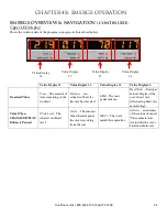
Page 46: ...m 800 426 6570 636 272 7100 42 EMERGE OVERVIEW NAVIGATION Numeric Keypad Upper LED Display HRC Cruise Control Increase Workload Decrease Workload Warning Decal Change Display Workout Finder Target HRC Start Enter Reading Rack Upper LED Displays ...

Page 47: ...ledge on the console that can be used to hold a book magazine e reader or tablet computer during a workout Warning Decal Important safety information for users to review prior to using the equipment Target HRC Starts a Target HRC workout See Program Descriptions Section Enter Press this key to confirm a selection in a preset workout HRC Cruise Control Engages Heart Rate Control to allow the equipm...

Page 48: ...ance An estimate of how far the user has traveled RPM The users pedal cadence Heart Rate Beats per minute display of the user s heart rate when using heart rate monitoring Value When CHANGE DISPLAY Button is Pressed Work Level The selected workload level Watts The amount of mechanical power the unit is receiving from the user METs The user s metabolic equivalent Calories an estimate of the calorie...

Page 49: ...t program time Weight Sets the default user weight Pause Duration Time the console will wait before resetting when in a program Sleep Sets the time the unit sit unused before the console goes into sleep mode Sound on or off RPM Not used Setting the Sleep Timer The following steps allow the Sleep Timer time without use after which the console will go dim to be adjusted The default Sleep Timer is 30...

Page 50: ...rized Service representative please visit www truefitness com CLEANING THE EQUIPMENT After Each Use Use GymWipes Antibacterial wipes or spray a solution of 30 parts water to 1 part mild detergent to dampen a soft cloth and wipe all exposed surfaces Use a LCD screen cleaner or spray a solution of 1 part 91 isopropyl alcohol and 1 part water to dampen a soft cloth and wipe the surface of the console...

Page 51: ...t all components for abnormal or premature wear Inspect and lubricate pedal threads on bike to prevent corrosion CAUTION Use only TRUE Fitness certified service providers LONG TERM STORAGE When the bike is not in use for any length of time turn it off Make sure that the power cord is unplugged from the power source and is positioned so that it will not become damaged or interfere with people or ot...

Page 52: ...ntact information for the closest dealer You may also contact TRUE Fitness customer support team by calling 800 883 8783 or e mailing us at service truefitness com Monday Friday during normal business hours TRUE FITNESS SERVICE DEPARTMENT 865 HOFF ROAD ST LOUIS MO 63366 1 800 883 8783 HOURS OF OPERATION 8 30 A M 5 00 P M CST E MAIL service truefitness com CONTACTING SALES Interested in TRUE Produc...

Page 53: ...e not sure if the actual product is damaged or not You must sign the bill of lading as damaged when accepting the shipment Once you have opened the box and you have determined something is indeed damaged please gather the serial number model number description and photos of damages Please make sure the photos include the damaged product as well as the damaged box the product arrived in Contact the...

Page 54: ...tomer Service Department if applicable Battery is discharged Charge the battery overnight with optional power supply if applicable Motor control board damaged Contact True Fitness Customer Service Department Unit resets or pauses randomly Damaged power cord Replace power cord Power cord not fully seated in socket Inspect power connection at the unit and outlet Insufficient power Verify output volt...

Page 55: ...quency or is encoded Polar equip or compatible receiver use 4 8kHz un encoded receiver The battery inside the transmitter belt is depleted replace the transmitter belt with a compatible transmitter belt Another user wearing a compatible transmitter strap is within 3 foot 1 meter of the unit Move the units so that there is more space in between units Environmental interference from high voltage pow...

Page 56: ...y Maximize your workout while minimizing your equipment footprint The new sleek design and low step over height is designed for those seeking a realistic cycling experience The fore and aft seat adjustment offers a wide range of customization P r e m i u m F i t n e s s E q u i p m e n t S i n c e 1 9 8 1 ES900 Truefitness com 800 426 6570 636 272 7100 52 ...

Page 57: ... Step Over Height REGULATORY APPROVALS ETL UL1647 CSA EXTRAS Accessories Water Bottle Holder 2 removable Accessory Tray Over Molded Reading Rack Tablet Holder PHYSICAL SPECIFICATIONS Footprint 44 L x 24 W 111 cm x 61 cm Machine Weight 122 lbs 55 kg Maximum User Weight 350 lbs 159 kg Step Over Height 16 75 42 5 cm Portability 2 Front Transport Wheels WARRANTY Warranty Type Residential Frame Lifetim...

Page 58: ... longer an authorized TRUE dealer then TRUE Limited Warranty service may be obtained by contacting TRUE directly at TRUE Fitness Service Department 865 Hoff Road St Louis MO 63366 1 800 883 8783 Hours of operation 8 30am 5 00 pm CST The above Limited Warranty is subject to and will be in accordance with the conditions set forth below 1 This Limited Warranty can be processed only if the Warranty Re...

Page 59: ... labor requires TRUE s written approval BIKE SERIAL NUMBERS The ES900 upright bike comes with two serial numbers one on the base and one on the display console see diagram below The serial number on the base is located on bottom of the frame The console serial number is located on the bottom right side of each console Please write down your serial numbers below and keep for your records CONSOLE SE...

Page 60: ...te ____ c Referral ____ d Gym Club ____ e Current Customer ____ f Other_______________ 2 The primary user s is ____ a Male ____ b Female ____ c Both 3 Do you currently belong to a health club ____ a Yes ____ b No 4 Your age group ____ a Under 25 ____ b 25 35 ____ c 36 45 ____ d 46 55 ____ e 56 65 ____ f 65 5 What was the primary reason you bought a TRUE product Check only one ____ a Design Appeara...

Reviews: