background image

CHAPTER 4: PROGRAMMING & OPERATION 

Truefitness.com / 800.426.6570 / 636.272.7100 

50


CAUTION:

The safety key must be in place on the treadmill console, and should be attached to the user’s clothing. The treadmill will 

not operate if the safety key is not attached to the console. 

HEART RATE MONITORING: 

This treadmill can monitor a user’s heart rate using either a Polar® compatible chest strap or the metal grips on the hand 

rails (called contact heart rate or CHR pads). A chest strap transmits the user’s heart rate to the treadmill via radio, and the 

CHR pads connect to a special computer circuit to extract the user’s heart rate. 

Chest Strap Heart Rate Monitoring:


Although this treadmill functions fine without using the heart rate monitoring feature, this kind 

of monitoring gives valuable feedback on the user’s effort level. 

Using c

hest strap

 or Bluetooth


monitoring also allows users to use Heart Rate Control, the most advanced exercise control 

system available. 

When users wear a Polar® compatible transmitter strap

 or a Bluetooth transmitter

, the treadmill 

will display the user’s heart rate as a digital beats-per-minute (bpm) readout.  

A chest strap

 should be worn directly against the user’s skin, about 1-2 inches below the pectoral 

muscles/breast line. Women should be careful to place the


transmitter below their bra line. 

*Bluetooth transmitters should be worn in accordance with the manufacturer's documentation.

Initially the transmission signal for heart rate may be erratic or non-existent. Some moisture is

necessary between the strap and the user’s skin for proper transmission. Sweat from exercise

works best, but ordinary tap water may be used prior to the workout if desired.

A Note on Chest Strap Heart Rate Monitoring: 

The chest strap produces a radio signal that the treadmill reads and registers as the user’s heart rate. The accuracy of a 

reading may be affected when outside interference is present. 

Contact Heart Rate (CHR): 

The CHR system will let the user monitor their heart rate without wearing a chest strap. When using the CHR system 

users should gently grasp the CHR pads with both hands. Within 30 seconds, the user’s heart rate should be displayed as a 

digital bpm readout (during the first 30 seconds the system is analyzing and locking in the user’s heart rate). Users should 

exercise with smooth body motions and breathe regularly. It is best to avoid talking while using the CHR system, as 

talking will cause unrepresentative heart rate spikes of 5 to 10 bpm. To ensure an accurate reading, the user’s hands should 

be clean, free of both dirt and hand lotions.  

*For increased safety and accuracy the CHR system should only be used at speeds of 4 mph or lower (CHR readings are

less accurate due to large muscle movements above this speed).

A Note on CHR Accuracy:

CHR monitoring may be less accurate than chest strap monitoring since the heart rate signals are much stronger at the 

chest. When using a HRC workout, it is best to use a chest strap because of the stronger and more accurate readings. 


CAUTION: 

Do not use the contact heart rate grips as a handlebar during a workout.

Summary of Contents for TE900

Page 1: ... Assembly Guide Warranty Card Included Revision 060117 TE900 TREADMILL OWNER S MANUAL Transcend Console Escalate15 Console Escalate9 Console ...

Page 2: ...library 29 international manuals ﻫﺎﻡ ﺟﻣﻳﻊ ﺍﻟﻣﻧﺗﺟﺎﺕ ﻫﻲ ﺍﻟﻣﻌﺭﻭﺿﺔ ﺍﻟﻧﻣﻭﺫﺝ ﺗﺧﺗﻠﻑ ﻗﺩ ﺍﻟﻔﻌﻠﻲ ﺍﻟﻣﻧﺗﺞ ﺗﺳﻠﻳﻣﻬﺎ ﻭ ﺍﻟﻣﻧﺗﺞ ﻣﻭﺍﺻﻔﺎﺕ ﻭﺍﻟﺑﺭﺍﻣﺞ ﺍﻟﻣﻳﺯﺍﺕ ﻟﻠﺗﻐﻳﻳﺭ ﻗﺎﺑﻠﺔ ﺇﺷﻌﺎﺭ ﺩﻭﻥ ﻟ ﻳﺻﻝ ﻣﺎ ﻣﻌﻅﻡ ﺍﻵﻥ ﺣﺗﻰ ﺍﻟﻣﺎﻟﻙ ﺩﻟﻳﻝ ﺯﻳﺎﺭﺓ ﻳﺭﺟﻰ www truefitness com ﻟﻠﻣﺳﺗﻧﺩﺍﺕ ﻟﻐﺎﺕ ﻓﻲ ﻳﺭﺟﻰ ﺇﺿﺎﻓﻳﺔ ﺯﻳﺎﺭﺓ www truefitness com document library 29 international manuals WICHTIG Alle hier gezeigten Produkte sind Prototypen Das tatsächliche Produkt...

Page 3: ...ll product line has made TRUE successful and is a trademark of the TRUE heritage TRUE s patented Heart Rate Control technology is just one of the remarkable ways we deliver simple and superior performance every user can enjoy and most importantly use to achieve personal health and fitness goals TRUE strives to perfect biomechanically correct and orthopedically comfortable functional products Wheth...

Page 4: ...view Touchscreen Introduction Touchscreen Navigation Web Browser Bluetooth Audio TV Controls Outside Interactive Advanced Console Functions 71 Chapter 4B Escalate15 Operation 89 91 95 97 99 115 117 123 131 131 132 133 133 134 134 134 135 135 135 Escalate15 Overview Console Navigation TV Controls Bluetooth Audio Advanced Console Functions Chapter 4B Escalate9 Operation Escalate9Overview Console Nav...

Page 5: ...y maintenance activity Do not handle the plug with wet hands WARNING To reduce the risk of burns fire electric shock or injury it is imperative to connect each product to a properly grounded 110V electrical outlet A risk of electrical shock may result from improper connection of the equipment s grounding conductor Check with a qualified electrician if you are unsure about proper grounding techniqu...

Page 6: ...s product so the power cord plug is accessible to the user Keep the power cord away from heated surfaces Do not pull the equipment by the power cord or use the cord as a handle Do not run the power cord along the side or under the treadmill If the electrical supply cord is damaged it must be replaced by the manufacturer an authorized service agent or a similarly qualified person to avoid a hazard ...

Page 7: ...service this equipment Avoid the possibility of bystanders being struck or caught between moving parts by making sure that they are out of reach of the equipment while it is in motion This appliance can be used by children aged from 8 years and above and persons with reduced physical sensory or mental capabilities or lack of experience and knowledge if they have been given supervision or instructi...

Page 8: ... 800 426 6570 636 272 7100 4 CHAPTER 1 SAFETY INSTRUCTIONS SPACE REQUIREMENTS TRUE s recommendation is to leave a minimum of 20 0 5m on each side of the treadmill and a 79 2 m safety zone at the rear of the treadmill ...

Page 9: ...uipment is in use to ensure an immediate halt of all treadmill belt activity if the user is unable to continue Safety Key Feature Number Safety Key Clip 1 Safety Key Pull Cord 2 Safety Stop Engagement Indicator Safety Stop Reset Button 3 Console Rack 4 3 2 1 4 Safety Key E Stop Overview CHAPTER 1 SAFETY INSTRUCTIONS ...

Page 10: ...al workout parameters identified within this owner s manual Shown to the left is the engaged position of the safety key e stop Note the safety stop outer sleeve that covers the safety stop to denote the engaged position When the safety stop is engaged all treadmill belt activity will cease and the following error message will appear on the console advising the safety stop is engaged INSERT SAFETY ...

Page 11: ...rovided with the product If it will not fit the outlet have a proper outlet installed by a qualified electrician Do not remove the motor cover or you may risk injury due to electric shock The 120 V model is for use on a nominal 120 V circuit and has a grounding plug that looks like the plug illustrated in figure A Make sure the product is connected to an outlet having the same configuration as the...

Page 12: ...CHAPTER 1 SAFETY INSTRUCTIONS Truefitness com 800 426 6570 636 272 7100 8 ...

Page 13: ...hat may be worn damaged or missing To replace any worn or missing warning decals contact TRUE FITNESS by visiting www truefitness com or contact customer service at 800 883 8783 COMPLIANCES This equipment complies with all applicable codes and regulations For a complete list of compliances please visit www truefitness com ...

Page 14: ... are in doubt as to whether the treadmill is properly grounded Do not modify the plug provided with the treadmill if it will not fit the outlet Have a proper outlet installed by a qualified electrician Read and understand all instructions and warnings prior to use Obtain a medical exam before beginning any exercise program If at any time during exercise you feel faint dizzy or experience pain stop...

Page 15: ...1 B Frame 1 C Pedestal Left 1 D Pedestal Right 1 E Handrail Left 1 F Handrail Right 1 G Optional Decline Bracket Left 1 H Optional Decline Bracket Right 1 I Lower Console Rack Cover 1 J Hand Grip Assembly Left 1 K Hand Grip Assembly Right 1 L Rear Console Cover 1 M 1 N 1 O 1 Lower Shoulder Cover Left Lower Shoulder Cover Right Power Cord ...

Page 16: ... 16 6 point socket short extension and ratchet Long nose pliers small optional Wire cutters small optional Item Description Qty Item Description Qty a Bolt M8 x P1 25 x 25 10 i 1 b 2 j 8 c 10 k 8 d 2 l 8 e 1 f 2 g 12 h 27 Screw M5 x P0 8 x 10 Lock Washer M8 Lock Nut M8 x P1 25 Cap Motor Cover Screw Cap Motor Cover Screw Bolt 1 4 20 x 3 4 Screw M4 x P0 7x12 m n o p 8 1 1 2 Bolt M5 x P0 8 x 60 Bolt ...

Page 17: ...TION Use caution when assembling treadmill Unpacking and assembling of this treadmill is a two person task Remove all treadmill components from packaging Step 1 Remove Motor Cover a Remove the screw o and washer n from the motor cover and set to the side b Remove the motor cover from the treadmill frame B ...

Page 18: ... Pedestal Installation a Secure the pedestals to the treadmill frame using nine Bolts M8 x 25 c nine M8 lock washers a and one M8 lock nut d where shown Note Do not fully tighten the hardware used in this step yet Note Ensure the pedestal cables are routed between the treadmill frame and pedestal support brace as shown ...

Page 19: ...l the washer and nut on the coaxial cable Note Fig 3 1 is how the frame cable connections appear coming out of the shipping box Fig 3 1 illustrates the frame cable connections for the Emerge LED and 9 TFT consoles Fig 3 2 illustrates the frame cable connections for the Transcend and 15 TFT consoles Note the different auxiliary power supply connection points between the two pictures based on the co...

Page 20: ...the wire coming from the bottom of the Contact Heart Rate CHR grip assembly to the corresponding wire located in the pedestal arm as shown b Secure each CHR grip assembly to the pedestal arm with four screws and four lock washers Note Confirm each grip assembly is assembled on the correct pedestal using the left and right orientation stickers on them ...

Page 21: ...ole rack onto the pedestals by resting the console rack tubing on top of the pedestal tubing cradles Caution Do not pinch cabling during this step b Install eight bolts 5 16 x 1 1 2 and eight external tooth lock washers through the pedestal tubing cradle and console rack but do not tighten c Tighten all hardware from steps 2a 6c d Install four M4 x 12 screws and tighten ...

Page 22: ...stallation a Connect all wires from the left and right pedestal arms to the wires from the upper console rack cover as shown all cables will be connected regardless of console option Do not over torque the coax TV cable b Route all cables into the underside of the upper console rack cover as shown to prevent wire pinching when installing the bottom console rack cover ...

Page 23: ...e rack first Next carefully raise up the front edge while making adjustments so the safety clip docking bracket and long screw boss passes up through the safety key mechanism Warning Do not force the installation of the bottom cover Hardware Required 9 bolts M4 x 12 Step 8 Shoulder Trim Assembly a Secure the left and right shoulder trim assemblies to the console rack using 14 bolts M4 x 12 Hardwar...

Page 24: ... continued Step 9 Handrails a Fully insert the handle and then loosely install the four bolts 1 4 20 x 3 4 two for each handrail While slightly rotating the handle to best align the seams and holding inwards securely tighten the bolts Caution When starting the bolts be careful not to cross thread them ...

Page 25: ...d Step 10 Safety Key a Locate the Safety Key attached to the console rack b Attach the Safety Key clip to the anchor plate located on the console rack when not working out c Attach the safety key clip to clothing at the beginning of any workout CAUTION Read treadmill Owner s Manual before attempting any workout ...

Page 26: ...Remove the leveling feet from the treadmill frame as shown CHAPTER 2 ASSEMBLY INSTRUCTIONS TREADMILL ASSEMBLY STEPS continued Step 12 Leveling Feet Decline Kit Truefitness com 800 426 6570 636 272 7100 22 ...

Page 27: ... feet into the optional decline kit holes as shown CHAPTER 2 ASSEMBLY INSTRUCTIONS Truefitness com 800 426 6570 636 272 7100 23 TREADMILL ASSEMBLY STEPS continued Step 12 Leveling Feet Decline Kit Continued Note The bracket is left and right side sensitive so confirm you are using the correct bracket Hardware Required 8 bolts 1 4 20 x 3 4 ...

Page 28: ...loor and not on cardboard packaging etc b Using a 15 16 inch open end wrench loosen nut A on Right Rear Foot only side adjustable c Using a level or estimating by sight turn section B of foot clockwise or counter clockwise using a 7 8 inch open end wrench to level the rear of treadmill d Tighten nut A until it is secured against bottom of treadmill Note The recommended gap between A and B is 1 4 o...

Page 29: ...ole Cover Assembly a Secure the rear console cover assembly to the console mast assembly using two bolts M5 x 10 CAUTION Make sure cabling is NOT pinched during installation Note For specific console assembly instructions see the corresponding section at the end of Chapter 2 Assembly Instructions Hardware Required 2 bolts M5 x 10 ...

Page 30: ...M5 x 60 1 retainer power cord 1 spacer Note The 110V spacer is 1 3 4 long CIRCUIT BREAKER In the event the current drawn by the treadmill exceeds a specified threshold value the Circuit Breaker will operate the button will pop out and open the circuit If this should occur please wait 10 minutes and then reset the Circuit Breaker by pressing the button in on Circuit Breaker If it does not reset or ...

Page 31: ...CHAPTER 2 ASSEMBLY INSTRUCTIONS TREADMILL ASSEMBLY STEPS continued Step 17 Wiring Diagrams Truefitness com 800 426 6570 636 272 7100 27 ...

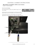
Page 32: ... Coaxial Cables Locate the Ground Wire Coaxial Cable and Data Cable USB coming from the console Partially thread the bottom two console attachment screws into the console CHAPTER 2 ASSEMBLY INSTRUCTIONS Truefitness com 800 426 6570 636 272 7100 28 TREADMILL ASSEMBLY STEPS continued Transcend Console Assembly ...

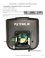
Page 33: ...to the keyholes on the console mast assembly Partially thread the top two console mounting screws and then fully tighten all four console mounting screws using a long Phillips screwdriver Item Description Quantity 4 Ground Wire 1 5 Data Cable USB 1 4 5 CHAPTER 2 ASSEMBLY INSTRUCTIONS Truefitness com 800 426 6570 636 272 7100 29 TREADMILL ASSEMBLY STEPS continued Transcend Console Assembly ...

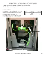
Page 34: ...arts as shown below Note Position the rubber boot over the coaxial cable connection point Item Description Quantity 6 Data Cable USB 1 7 Coaxial Cable 1 6 7 CHAPTER 2 ASSEMBLY INSTRUCTIONS Truefitness com 800 426 6570 636 272 7100 30 TREADMILL ASSEMBLY STEPS continued Transcend Console Assembly ...

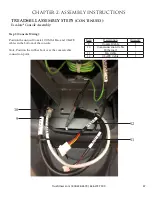
Page 35: ...ing Connect the Auxillary Power Supply AUXPS and Communication Cable Ethernet to the corresponding ports on the console placing any excess cord length inside the console 8 9 CHAPTER 2 ASSEMBLY INSTRUCTIONS Truefitness com 800 426 6570 636 272 7100 31 TREADMILL ASSEMBLY STEPS continued Transcend Console Assembly ...

Page 36: ... the corresponding location on the console mast assembly marked GND using the screw that is currently there Position the unused Fan and CSAFE cables inside the pedestal Item Description Quantity 10 Ground Wire 1 11 Ferrite 1 12 Wire Tie 1 CHAPTER 2 ASSEMBLY INSTRUCTIONS Truefitness com 800 426 6570 636 272 7100 32 TREADMILL ASSEMBLY STEPS continued Transcend Console Assembly ...

Page 37: ...cate Cable Connection Locate the identified cable connection A and the adjacent wire tie A CHAPTER 2 ASSEMBLY INSTRUCTIONS Truefitness com 800 426 6570 636 272 7100 33 TREADMILL ASSEMBLY STEPS continued Transcend Console Assembly ...

Page 38: ...ate the cable connection identified in Step 5 Cable connection A is no longer used and cable connection B will be connected to the 12V power adapter A B CHAPTER 2 ASSEMBLY INSTRUCTIONS Truefitness com 800 426 6570 636 272 7100 34 TREADMILL ASSEMBLY STEPS continued Transcend Console Assembly ...

Page 39: ...n below and use two wire ties to secure the cables and 12V power adapter to the motor pan ensuring the inline cable connector is positioned between both wire ties Trim any excess wire tie length using wire cutters Item Description Quantity 13 AC Power Adapter Cable 1 14 AUXPS 1 15 Wire Tie 2 14 13 15 15 CHAPTER 2 ASSEMBLY INSTRUCTIONS Truefitness com 800 426 6570 636 272 7100 35 TREADMILL ASSEMBLY...

Page 40: ...Data Cables Locate the Ground Wire Coaxial Cable and Data Cable USB coming from the console Partially thread the bottom two console attachment screws into the console 2 1 3 CHAPTER 2 ASSEMBLY INSTRUCTIONS Truefitness com 800 426 6570 636 272 7100 36 TREADMILL ASSEMBLY STEPS continued Escalate15 Console Assembly ...

Page 41: ...o the keyholes on the console mast assembly Partially thread the top two console mounting screws and then fully tighten all four console mounting screws using a long Phillips screwdriver Item Description Quantity 4 Ground Wire 1 5 Data Cable USB 1 5 4 CHAPTER 2 ASSEMBLY INSTRUCTIONS Truefitness com 800 426 6570 636 272 7100 37 TREADMILL ASSEMBLY STEPS continued Escalate15 Console Assembly ...

Page 42: ...cess cord length inside the console Note Position the rubber boot over the coaxial cable connection point Item Description Quantity 6 Auxillary Power Supply Cable 1 7 Data Cable USB 1 8 Coaxial Cable 1 9 Communication Cable Ethernet 1 6 7 8 9 CHAPTER 2 ASSEMBLY INSTRUCTIONS Truefitness com 800 426 6570 636 272 7100 38 TREADMILL ASSEMBLY STEPS continued Escalate15 Console Assembly ...

Page 43: ...responding location on the console mast assembly marked GND using the screw that is currently there Position the unused Fan and CSAFE cables inside the pedestal Item Description Quantity 10 Ground Wire 1 11 Ferrite 1 12 Wire Tie 1 12 11 10 CHAPTER 2 ASSEMBLY INSTRUCTIONS Truefitness com 800 426 6570 636 272 7100 39 TREADMILL ASSEMBLY STEPS continued Escalate15 Console Assembly ...

Page 44: ...ate Cable Connection Locate the identified cable connection A and the adjacent wire tie A CHAPTER 2 ASSEMBLY INSTRUCTIONS Truefitness com 800 426 6570 636 272 7100 40 TREADMILL ASSEMBLY STEPS continued Escalate15 Console Assembly ...

Page 45: ...te the cable connection identified in Step 5 Cable connection A is no longer used and cable connection B will be connected to the 12V power adapter A B CHAPTER 2 ASSEMBLY INSTRUCTIONS Truefitness com 800 426 6570 636 272 7100 41 TREADMILL ASSEMBLY STEPS continued Escalate15 Console Assembly ...

Page 46: ...n below and use two wire ties to secure the cables and 12V power adapter to the motor pan ensuring the inline cable connector is positioned between both wire ties Trim any excess wire tie length using wire cutters Item Description Quantity 13 AC Power Adapter Cable 1 14 AUXPS 1 15 Wire Tie 2 14 13 15 15 CHAPTER 2 ASSEMBLY INSTRUCTIONS Truefitness com 800 426 6570 636 272 7100 42 TREADMILL ASSEMBLY...

Page 47: ... Cable Locate the ground wire and Data Cable USB coming from the console Partially thread the bottom two console attachment screws into the console 1 2 CHAPTER 2 ASSEMBLY INSTRUCTIONS Truefitness com 800 426 6570 636 272 7100 43 TREADMILL ASSEMBLY STEPS continued Escalate9 Console Assembly ...

Page 48: ...to the keyholes on the console mast assembly Partially thread the top two console mounting screws and then fully tighten all four console mounting screws using a long Phillips screwdriver Item Description Quantity 3 Ground Wire 1 4 Data Cable USB 1 3 4 CHAPTER 2 ASSEMBLY INSTRUCTIONS Truefitness com 800 426 6570 636 272 7100 44 TREADMILL ASSEMBLY STEPS continued Escalate9 Console Assembly ...

Page 49: ...s and any excess cable length in the bottom of the console Connect the auxillary power supply AUXPS cable to the corresponding console port Item Description Quantity 5 Auxillary Power Supply Cable 1 6 Data Cable USB 1 5 6 CHAPTER 2 ASSEMBLY INSTRUCTIONS Truefitness com 800 426 6570 636 272 7100 45 TREADMILL ASSEMBLY STEPS continued Escalate9 Console Assembly ...

Page 50: ...ound wire ring terminal to the corresponding location on the console mast assembly marked GND using the screw that is currently there Item Description Quantity 6 Ground Wire 1 7 Ferrite 1 8 Wire Tie 2 6 7 8 CHAPTER 2 ASSEMBLY INSTRUCTIONS Truefitness com 800 426 6570 636 272 7100 46 TREADMILL ASSEMBLY STEPS continued Escalate9 Console Assembly ...

Page 51: ...on the rubber boot over the coaxial cable connection point Item Description Quantity 9 Coaxial Cable 1 10 Communication Cable Ethernet 1 11 Fan Cable 1 12 CSAFE Cable 1 10 12 11 9 CHAPTER 2 ASSEMBLY INSTRUCTIONS Truefitness com 800 426 6570 636 272 7100 47 TREADMILL ASSEMBLY STEPS continued Escalate9 Console Assembly ...

Page 52: ...100 48 TREADMILL OVERVIEW Quick Access Keys Contact Heart Rate Pad Console Assembly Safety E Stop Key Straddle Covers Belt Decline Foot and Leveling Feet On Off Switch Circuit Breaker and Power Cord Belt Adjustment Bolts Contact Heart Rate Pad Adjustable Soft Select ...

Page 53: ...The safety stop reset button should be attached to the user s clothing The treadmill will not operate if the safety stop reset button is in the engaged position Belt The moving surface of the treadmill on which the user walks or runs Straddle Covers Stationary covers on either side of the belt which allows the user to safely straddle the belt during startup or in the event of an emergency Belt Adj...

Page 54: ...al for heart rate may be erratic or non existent Some moisture is necessary between the strap and the user s skin for proper transmission Sweat from exercise works best but ordinary tap water may be used prior to the workout if desired A Note on Chest Strap Heart Rate Monitoring The chest strap produces a radio signal that the treadmill reads and registers as the user s heart rate The accuracy of ...

Page 55: ...te with how they feel to ensure safety and comfort Consult a physician to determine target heart rate Using heart rate to control a workout takes the guesswork out of the workout settings Consult a physician before using heart rate controlled workouts for advice on selecting a target heart rate range Also it is important to use the treadmill for several workouts in the manual mode while monitoring...

Page 56: ...grams vary depending on the console option selected Please refer to the chart to the below for assistance in determining which programs are available on this unit Console Options Transcend16 Escalate15 YES YES YES YES YES YES Quick Start A workout in which the user controls all settings The workout continues until it is ended by the user Manual Users enter their weight workout time or distance The...

Page 57: ...allows users to choose the number of calories they wish to burn within a specified workout time The treadmill will control SPEED and INCLINE within the limits set by the user to attain this goal Cardio Challenge SPEED and INCLINE increase to a maximum at the mid point of the workout then decrease to the finish INCLINE and SPEED changes affect the current segment only Walk and Run Intervals Uses SP...

Page 58: ...eds the target by more than 12 BPM the workout will end and Cool Down will begin HRC Target Users choose their target heart rate The treadmill begins in MANUAL control The user should gradually increase the workout intensity until heart rate is within 10 bpm of their target At this point the treadmill takes over to control speed and incline to maintain heart rate within a few beats of the user s t...

Page 59: ...k 2 miles and 4miles that put the treadmill in control of pace by selecting the user s target heart rate The treadmill begins in MANUAL control The user should gradually increase the workout intensity until heart rate is within 10 bpm of their target At this point the treadmill takes over to control speed and incline to maintain heart rate within a few beats of the user s target Fitness Test A fit...

Page 60: ...long Niagara Falls on the Canadian border Start at the Niagara Power Plant and enjoy the views along the river scouting tourists on the U S side as you run under Rainbow Bridge gateway to the U S On your return you ll enjoy spectacular sweeping views of the falls Don t worry about overheating as the mist will be sure to keep you cool Hills of Bali We hope you will enjoy this run through the beauti...

Page 61: ...is where the action is This is evident when you run to this video Runners of all kinds even a few bikes and a horse drawn carriage greet you as you run through New York s Central Park On average 25 million people visit Central Park every year Now you can visit from the comfort of your club or gym thanks to TRUE s Outside Interactive run through the park New Balance Falmouth Road Race Test your end...

Page 62: ...Truefitness com 800 426 6570 636 272 7100 58 CHAPTER 4A TRANSCEND OPERATION TRANSCEND OVERVIEW Touchscreen Display Cooling Fan Headphone Jack USB Jack Auxiliary LCD Display Reading Rack Warning Decal ...

Page 63: ...update the console software Auxiliary LCD Display Displays workout data that can be easily viewed regardless of which mode is displayed on the Touchscreen Display Available on the 16 model only Reading Rack This ledge on the console can be used to hold a book magazine e reader or tablet computer during a workout Cooling Fan Integrated fan that delivers a cooling flow of air during a workout Warnin...

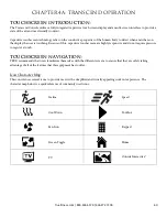
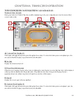
Page 64: ...eens are highly responsive and do not require pressure to register a touch TOUCHSCREEN NAVIGATION TRUE recommends that users familiarize themselves with the different screens to ensure that they are safely taking advantage of all of the features that this equipment has to offer Icon Character Map This console uses several icons to provide users with a simplified and visually appealing workout expe...

Page 65: ...orkout continues until it is ended by the user B Safety Instructions Displays a list of safety instructions for users to review prior to beginning a workout C Workout Finder Displays preset workouts categorized by goal focus categories D Language Options Allows users to choose between 12 language options E TV Displays TV interface without starting a workout F Screen Lock When the screen lock is he...

Page 66: ...ategory preview window B Workouts can also be viewed in an uncategorized list by touching the Show All Workouts button C Workout Data Entry Screens Workout data entry screens allow the user to input their personal information or workout goals prior to beginning a preset workout To set a value touch the heading A of the value and adjust the slider B to the desired setting or manually enter a value ...

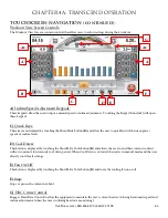
Page 67: ...evel C Heart Rate Information When the user is wearing a heart rate chest strap or utilizing the contact heart rate system their heart rate will be displayed in beats per minute bpm and in the graphic meter The graphic meter is based on age and will gauge the user s approximate heart rate within 3 target levels Weight Loss Aerobic or Performance D Speed Displays the current speed of the treadmill ...

Page 68: ... Cool Down This button is displayed by touching the Show Hide Tools button B and allows the user to end their current workout with a two minute low intensity cool down period When Cool Down is activated the unit is in manual mode and the user directly controls all settings E Fan On Off This button is displayed by touching the Show Hide Tools button B and turns the cooling fan on or off F Stop Stop...

Page 69: ...display window B to scroll through the available screens Workout Summary Screen At the end of a workout the Summary Screen will display an overview of the workout data The workout data can be exported to a USB drive by inserting the USB drive into the console s USB port and touching the Save button A If the user requires more time to view the summary or to save the workout to a USB device they can...

Page 70: ... the user to switch back and forth between full screen and regular mode C Keyboard Displays the onscreen keyboard to allow users to input text D Home Displays the browsers home page See advanced console options for instructions on setting the homepage E Address Bar Displays the web address of the page that is being displayed and allows users to input the addresses of pages they wish to visit F Cle...

Page 71: ...etooth and press the Bluetooth Button B to search for devices The console will complete a scan for available Bluetooth devices Once the scan is complete simply touch the name of the desired device C to begin the pairing process If the device is not listed verify that it the Bluetooth is enabled and that the device is discoverable Then touch the Bluetooth logo D to re scan for the Bluetooth devices...

Page 72: ...st For Android devices press Accept F to accept the request Once the Bluetooth pairing request has been accepted the playback screen will be displayed During playback users can control volume G pause advance or replay tracks by using the navigation buttons H and toggle between available audio sources by touching the Change Audio Button I To disconnect the Bluetooth audio device simply touch the di...

Page 73: ... or Mutes the audio volume from the TV program B Change Audio Toggles between available audio sources C Channel Controls Used to display a full list of available channels or to change channels one at a time D Closed Captioning Toggles the closed captioning on or off This button will only be visible when the program displayed supports closed captioning E Screen Toggle Allows the user to switch back...

Page 74: ...he Change Audio Button A to create a truly unique workout Additionally the Workout View Screen controls and displays are still available when using this feature in standard mode The video can be stopped without ending the workout at any time by touching the Stop Button B To display the video in full screen mode simply touch the Screen Toggle Button C Audio Volume C can also be adjusted B C D C Tru...

Page 75: ...egins to flash release the logo and press and hold the lower right corner of the screen C Main Menu After successfully entering service mode the screen below will be displayed From this menu users can access all of the service mode features by navigating through the various menus A C B Menus can be accessed by touching the selection buttons Touch Exit to return to the home screen Truefitness com 8...

Page 76: ...nsole not the base unit C Tuner Type The type of TV tuner installed in the console D Software Version The current version of software that is installed on the console E Firmware Version The current version of firmware that is installed on the console F BIOS Version The current BIOS version that is installed on the console G System Software Sum Displays OS data that is used in the production of the...

Page 77: ...roduct Setup screen allows users to change the console configuration to match the unit on which it is installed To change the console configuration From the Main Menu touch the Setup button From the Setup Menu Press Product Setup A Touch the correct model number to select it B Touch the Save key to save the configuration C A B C Sub Categories can be accessed by touching the selection buttons Touc...

Page 78: ...nutes to complete Do not stand on the treadmill during the calibration procedure Verify that the machine is free of all parts and tools Keep children and animals at a safe distance Calibration Steps From the Main Menu press the Setup button From the Setup Menu press Calibration A Press the Calibrate key B When complete the console will display Calibration Successful WARNING The Potentiometer Value...

Page 79: ...ing the system s error log Setting the Clock From the Main Menu press the Setup button From the Setup Menu press the Clock Button A Touch the arrows B to adjust the date and time and use the slider button C to select AM or PM Once the correct time and date are entered touch the Next key D Use the slider E or swipe through the list of time zones until the correct time zone is shown in bold F Touch ...

Page 80: ...sole Additional Screen Saver Options Custom Screen Saver images can be deleted by touching the clear button D The amount of time the console must be idle before the screen saver engages can be adjusted by using the Screen Saver Time Slider E The Sleep timer is a function that will turn off the console s back light after a period of time to save energy The amount of time the console must be idle be...

Page 81: ...folder named facility case sensitive Importing Facility Images Touch the Facility Images button A Insert the USB drive that contains the images into the console s USB port Verify the images in the preview window B Touch the Save button C to save the images to the console Facility images can be deleted by touching the clear button D Once loaded correctly the facility Images will be displayed in the...

Page 82: ... touch TV Setup A Touch the type of signal that is being used to select it B Analog Digital or Both Digital is selected by default When analog is selected the user will need to choose the analog standard NTSC M for the United States Touch the Source Slider C to select between Antenna and Cable Verify that the correct Country is listed D Touch Enable Aux Input E to enable or disable the AUX inputs ...

Page 83: ...he TV Setup process Insert a blank USB drive into the console s USB port When all desired channels are listed in the Channel List A touch the Export Scan to USB Button B Importing TV Setup Data from USB Navigate to the TV Setup screen Insert the prepared USB stick into the console s USB Port Touch Import Scan from USB A Once the import process is complete verify that all channels are listed in the...

Page 84: ...ss the Add Channel Screen Use the Up Down Arrows C to adjust the values Standard Frequency Network and Channel Number Channel frequencies must be obtained from your television service provider Once all values are correct press OK D to save the channel Deleting Channels Touch the channel to be deleted to select it Press the Delete Channel Button A Press Delete Channel B to delete the selected chann...

Page 85: ...ls with minimal interruption to their workout Adding Channel Logos Navigate to the TV Advanced Screen A Touch the desired channel in the Channel List B to select it Touch the channel again to enter the logo screen Touch the logo C that corresponds to the selected channel Repeat these steps for each channel for which a logo is available D A B C Truefitness com 800 426 6570 636 272 7100 81 ...

Page 86: ...imply touch the Setup Connection button A and select the desired network from the list and enter the password if necessary and then press connect Enabling the Web Browser Touch the Web browser Enabled Slider B to enable it Accept the Internet Service Agreement Select a homepage by touching the Homepage Address Bar C and typing the web address of the desired page and pressing Enter to confirm the p...

Page 87: ...When enabled the console will attempt to read heart rate data from the contact heart rate grips before reading data from a wireless chest strap When this option is turned off telemetry heart rate will take priority D LCD Brightness Use the slider to adjust the brightness of the touchscreen display E System Sound Volume Use the slider to adjust the volume of the notifications and beeps that come fr...

Page 88: ...ummary Timeout Determines the amount of time the Workout Summary Screen will remain on the display By choosing the Off setting the summary will be displayed until ended by a user E Pause Timer This setting will limit the amount of time that a workout can be paused before it automatically ends By choosing the Off option the unit will remain paused until the user resumes or ends the workout F User P...

Page 89: ...that the belt has traveled Distance D is the amount of distance the belt has traveled since the last time the Clear Mileage button E was pressed The Distance Clear Mileage feature is helpful for tracking mileage in a preventive maintenance schedule Touching the Program Usage button F will provide a list of programs that have been used on the unit and how many times those programs have been used Th...

Page 90: ...nit is designed to receive 5 khz non coded transmissions only C Keypress When a quick access key is pressed on the unit NONE will change to indicate which key is being pressed In the event of a stuck key the key that is being engaged will display D Fan Speed Control Using the slider allows users to test the fan independent of a program E Target Speed Actual Speed Use the Target Speed slider to com...

Page 91: ...riodically release software updates to ensure users enjoy the best workout experience available To update the console software download the update program A from truefitness com and load the software to a blank USB drive by following the downloadable instructions DO NOT place the installation program on the USB stick The program must be run on a Windows based computer WARNING Disconnecting the pow...

Page 92: ...en calibration tool On the first screen displayed users can touch anywhere in the white area B and a small red box C will appear to verify screen function Touching the Calibrate button D will begin a touchscreen calibration During this process targets will appear on the screen and the user must press and hold each target until it turns red to complete the calibration Diagnostics Menu Advanced The ...

Page 93: ... ESCALATE15 OVERVIEW TFT Display Cooling Fan Headphone Jack USB Jack Truefitness com 800 426 6570 636 272 7100 Navigation Buttons Reading Rack Back Button Enter Stop Start TV Button Left Right Selection Buttons Up Down Selection Buttons ...

Page 94: ...sers to export workout data to an external USB drive or update the console software Headphone Jack Standard 3 5mm audio jack used to connect headphones to the console during media playback Back Button Used in navigate back within various console features Reading Rack This ledge on the console can be used to hold a book magazine e reader or tablet computer during a workout Enter Used to confirm sel...

Page 95: ...press the Enter button B C Quick Start Starts a Quick Start workout in which the user controls all settings The workout continues until it is ended by the user D Workout Finder Displays preset workouts categorized by goal focus categories E Safety Instructions Displays a list of safety instructions for users to review prior to beginning a workout F TV Displays TV interface without starting a worko...

Page 96: ...e viewed in an uncategorized list by selecting the Show All Workouts option C Workout Data Entry Screens Workout data entry screens allow the user to input their personal information or workout goals prior to beginning a preset workout To set a value A select it using the Left Right Selection Buttons B and then use the Up Down Selection Buttons C to adjust the value to the desired setting After al...

Page 97: ... and Pace B Incline Displays the current incline level C Heart Rate Information When the user is wearing a heart rate chest strap or utilizing the contact heart rate system their heart rate will be displayed in beats per minute bpm and in the graphic meter The graphic meter is based on age and will gauge the user s approximate heart rate within 3 target levels Weight Loss Aerobic or Performance D ...

Page 98: ... selection D Fan This tool toggles the cooling fan on and off E Cool Down Allows the user to end their current workout with a two minute low intensity cool down period When Cool Down is activated the unit is in manual mode and the user directly controls all settings F Change Units Allows users to change the data readouts between English Standard and Metric Units G HRC Cruise Control Engages Heart ...

Page 99: ... select More Time D and press the Enter Button C to extend the time that the summary remains on the screen TV CONTROLS This console has an integrated HDTV Tuner which allows the user to watch live programming in crisp clear high Definition The TV controls are built in to a Workout View Screen to allow the user to monitor their workout while enjoying their favorite shows While watching TV users can...

Page 100: ... Enter Button B to search for devices The console will complete a scan for available Bluetooth devices Once the scan is complete use the Up Down Selection Buttons C to select the desired device from the list of available devices and press Enter D If the device is not listed verify that it the Bluetooth is enabled and that the device is discoverable Use the Up Down Selection Buttons C to select Ref...

Page 101: ...ture to operate For iOS devices press Pair E to accept the request For Android devices press Accept F to accept the request Once the Bluetooth pairing request has been accepted the playback screen will be displayed During playback users can control volume by using the Up Down Selection Buttons G and advance or replay tracks by using the navigation buttons H G H E F Truefitness com 800 426 6570 636...

Page 102: ...h release the navigation button and press and hold the Enter Button C Main Menu After successfully entering service mode the Main Menu will be displayed From this menu users can access all of the service mode features by navigating through the various menus A C B Menus can be selected by using the Up Down Selection Buttons Touch Back to return to the home screen Truefitness com 800 426 6570 636 27...

Page 103: ...nsole not the base unit C Tuner Type The type of TV tuner installed in the console D Software Version The current version of software that is installed on the console E Firmware Version The current version of firmware that is installed on the console F BIOS Version The current BIOS version that is installed on the console G System Software Sum Displays OS data that is used in the production of the...

Page 104: ...up The Product Setup screen allows users to change the console configuration to match the unit on which it is installed To change the console configuration From the Main Menu select the Setup menu From the Setup Menu select Product Setup A Use the Selection Buttons B to select the correct model number C Press the Enter Button D to confirm the selection A C D Sub Categories can be selected by using...

Page 105: ...omplete Do not stand on the treadmill during the calibration procedure Verify that the machine is free of all parts and tools Keep children and animals at a safe distance Calibration Steps From the Main Menu press the Setup button From the Setup Menu select Calibration A Press the Enter Button B to begin calibration When complete the console will display Calibration Successful WARNING The Potentio...

Page 106: ...lect the Setup menu From the Setup Menu select Clock A Use the Left Right Selection Buttons B to select the desired value C Use the Up Down Selection Buttons D to adjust the value to the desired setting Once the correct time and date are entered select Next E and press Enter F Use the Up Down Selection Buttons G to scroll through the list of time zones until the correct time zone is shown in bold ...

Page 107: ...ages can be deleted by selecting Clear Current Slides E and pressing Enter B The amount of time the console must be idle before the screen saver engages can be adjusted by selecting Screen Saver Time F and using the Left Right Navigation buttons G to select the desired time The Sleep timer is a function that will turn off the console s back light after a period of time to save energy The amount of...

Page 108: ... Importing Facility Images Select Facility Images A and press Enter B Insert the USB drive that contains the images into the console s USB port Verify the images in the preview window C Select Save D using the Up Down Selection Buttons E and press Enter B to save the images to the console Facility images can be deleted by selecting the Clear F and pressing Enter B Once loaded correctly the facilit...

Page 109: ... the type of signal is being used C Then press Enter D to select the appropriate signal type Analog Digital or Both Digital is selected by default When analog is selected the user will need to choose the analog standard NTSC M for the United States Highlight the Source Slider E and Press Enter D to toggle between Antenna and Cable Verify that the correct Country is listed F Highlight Enable Aux In...

Page 110: ...le s USB port When all desired channels are listed in the Channel List A use the Up Down Selection Buttons B to highlight Export Scan to USB C and press Enter D Importing TV Setup Data from USB Navigate to the TV Setup screen Insert the prepared USB stick into the console s USB Port Highlight Import Scan from USB A using the UP Down Selection Buttons B and press Enter C Once the import process is ...

Page 111: ...ght Navigation Buttons C to select between the available values Standard Frequency Network and Channel Number Channel frequencies must be obtained from your television service provider Use the Up Down Selection buttons D to adjust each value Once all values are correct press Enter E to save the channel Deleting Channels Highlight the channel to be deleted Press the Back Navigation Button A Press E...

Page 112: ...nels with minimal interruption to their workout Adding Channel Logos Navigate to the TV Advanced Screen A Select the desired channel in the Channel List B and press the Enter Button C Select the logo D that corresponds to the selected channel and press Enter C to save Repeat these steps for each channel for which a logo is available D C A B C Truefitness com 800 426 6570 636 272 7100 108 ...

Page 113: ...e to allow users to save custom workouts to the console E Contact Heart Rate Has Priority When enabled the console will attempt to read heart rate data from the contact heart rate grips before reading data from a wireless chest strap When this option is turned off telemetry heart rate will take priority F LCD Brightness Adjusts the brightness of the TFT display G System Sound Volume Adjusts the vo...

Page 114: ...ill be displayed until closed by a user F Workout Summary Timeout Determines the amount of time the Workout Summary Screen will remain on the display By choosing the Off setting the summary will be displayed until ended by a user G Pause Timer This setting will limit the amount of time that a workout can be paused before it automatically ends By choosing the Off option the unit will remain paused ...

Page 115: ...s traveled Distance D is the amount of distance the belt has traveled since the last time the Clear Mileage E feature was used The Distance Clear Mileage feature is helpful for tracking mileage in a preventive maintenance schedule Statistics Menu Program Usage Selecting the Program Usage screen A will provide a list of programs that have been used on the unit and how many times those programs have...

Page 116: ...heart rate strap or simulator there is outside interference from another source This unit is designed to receive 5 khz non coded transmissions only C Fan Speed Control Allows users to test the fan independent of a program D Keypress When a quick access key is pressed on the unit NONE will change to indicate which key is being pressed In the event of a stuck key the key that is being engaged will d...

Page 117: ...sing Enter C but it is not recommended Diagnostics Menu Software Update TRUE may periodically release software updates to ensure users enjoy the best workout experience available To update the console software download the update program A from truefitness com and load the software to a blank USB drive by following the downloadable instructions WARNING Disconnecting the power source switching the ...

Page 118: ...te Software B and press Enter NOTE Do not power cycle the unit between the software and firmware updates After the installation of the software update highlight Load Firmware C and press Enter Following the installation of the software and firmware power cycle the unit to finalize the software update Diagnostics Menu Advanced The advanced screen contains multiple tools that are used in the product...

Page 119: ...26 6570 636 272 7100 115 CHAPTER 4C ESCALATE9 OPERATION ESCALATE9 OVERVIEW TFT Display Incline Keys Start Selection Buttons Selection Buttons Speed Keys Stop Reading Rack Headphone Jack Warning Decal Numeric Keypad USB Port ...

Page 120: ...er or tablet computer during a workout USB Port Allows users to export workout data to an external USB drive or update the console software Numeric Keypad A small panel of keys on the console that allow the user to quickly enter numeric data Headphone Jack Standard 3 5mm audio jack used to connect headphones to the console during media playback Warning Decal Important safety information for users ...

Page 121: ...er is able to select from various options to begin a workout A Workout Finder Displays preset workout selections by category B Quick Start Starts a Quick Start workout in which the user controls all settings until the workout is ended by the user C Language Options Allows users to choose between 12 language options A B C Truefitness com 800 426 6570 636 272 7100 117 ...

Page 122: ...hold the Next Selection Button to return to the previous screen Workout Data Entry Screens These screens allow users to input their personal information or workout goals prior to beginning a workout To set a value press the Selection Button for the value you wish to change A and use the and keys B to adjust the value to the desired setting Users may also manually enter a value using the Numeric Ke...

Page 123: ...y See Workout Data Screen Controls F Show Tools section B Time Displays the time elapsed for the current workout C Incline Shows the current incline of the treadmill D Speed Shows the current speed of the treadmill belt E Custom Data Display 2 By Default this display will show the calorie count for the current workout Users can also choose custom data points to be seen in this display See Workout ...

Page 124: ...ew Switches between the available Workout Data Screens B Cool Down Pressing this button allows the user to end their current workout with a two minute low intensity cool down period When Cool Down is activated the unit is in manual mode and the user directly controls all settings C HRC Cruise Engages Heart Rate Control to allow the equipment to maintain the user s current heart rate through automa...

Page 125: ...d To return to the Workout Data Screen press the Exit Quick Speed Selection Button B A B B A Truefitness com 800 426 6570 636 272 7100 121 CHAPTER 4C ESCALATE9 OPERATION CONSOLE NAVIGATION continued D Source Toggles between available audio sources which include TV if the console is equipped with a Broadcast Vision receiver and FM radio When an audio source is selected the user is given control ove...

Page 126: ...Selection button B will allow the Custom Data Displays to automatically toggle between data Pressing the Unit Selection Button D will change the units displayed between English and Metric Workout Summary Screen At the end of a workout the Summary Screen will display an overview of the workout data The workout data can be exported to another device by inserting a USB drive into the console s USB po...

Page 127: ...Workout Finder selection button C until the service screen displays Service Menu The first screen displayed after entering service mode is the Service Menu From this menu technicians can access all of the service mode features by selecting different categories To select a category use the scroll selection buttons A to highlight a category B Once a category has been selected press the enter selecti...

Page 128: ...n of software that is installed on the console C Units Displays the units the console is currently using as default U S or Metric D Max Speed The maximum speed the unit is able to reach E Min Speed The minimum Speed the unit is able to maintain F Max Incline The maximum percentage that the unit can be inclined G Min Incline The minimum percentage that the unit can be inclined H Max User Weight The...

Page 129: ...r selection button C to confirm the selection Utilities Menu Product Setup The product setup screen allows the technician to adjust model configuration incline range and speed range TRUE s recommendation is to only use the Setup Wizard to adjust these attributes After pressing the Setup Wizard Selection Button A simply follow the on screen instructions to complete the setup procedure WARNING Misco...

Page 130: ...te screen and insert the prepared USB drive into the console s USB port When the console recognizes the software it will show a message that reads Drive found and ready Press Update to begin Warning Improper use can render this machine inoperable To complete the update press the update selection button A WARNING Disconnecting the power source switching the unit off or pressing buttons on the conso...

Page 131: ...ss the back selection button E and the changes will be automatically saved Language Select a default Language for the unit All settings and workout data will be displayed in that language Units Choose how the workout data is displayed by default Save Workout Turns the saved workout feature on or off Heart Rate Priority Determines the order in which the unit reads heart rate data Cooldown Adjusts t...

Page 132: ... displayed until closed by a user Summary Timeout Determines the amount of time the Workout Summary Screen will remain on the display By choosing the Off setting the summary will be displayed until ended by a user Pause Time This setting will limit the amount of time that a workout can be paused before it automatically ends By choosing the Off option the unit will remain paused until the user resu...

Page 133: ... another source C Contact HR Ensures the unit is receiving the data by displaying the user s heart rate when the contact heart rate pads are gripped D Speed Incline Cal Speed Incline Cal calibration is selected by default in this menu To run a calibration press the enter selection button E and then follow the on screen instructions WARNING This process will take full control of the treadmill and c...

Page 134: ...ter selection button A but it is not recommended Statistics The statistics menu displays an overview of the treadmill s running data The overview includes distance time average speed maximum speed manual program count and preset program count These statistics can be exported to a connected USB drive by using the scroll selection buttons A to highlight the USB Export option B and pressing the enter...

Page 135: ...resentative please visit www truefitness com CLEANING THE EQUIPMENT After Each Use Use GymWipes Antibacterial wipes or spray a solution of 30 parts water to 1 part mild detergent to dampen a soft cloth and wipe all exposed surfaces Use a LCD screen cleaner or spray a solution of 1 part 91 isopropyl alcohol and 1 part water to dampen a soft cloth and wipe the surface of the console This helps remov...

Page 136: ... for a few minutes The belt should be centered on the running deck If the belt drifts off center you must make adjustments Important Failure to align the belt may cause the belt to tear or fray which may not be covered under the TRUE Fitness Warranty To stop the running belt press the STOP key Turn the treadmill off CAUTION For your safety use the power switch to turn off the treadmill before maki...

Page 137: ...t takes a few simple adjustments If you are unsure about this procedure call the TRUE Service Department Locate the belt adjustment bolts in the rear end caps of the treadmill Using the appropriate size Allen wrench or socket turn BOTH adjustment bolts clockwise turn Turn the treadmill on and start the belt and check if the slipping continues Repeat the above steps if additional adjustment is nece...

Page 138: ...age motor control board and heat sink motor compartment Move treadmill and vacuum underneath Lubricate elevation pivot points including rear stabilizing feet and the lift motor screw Lubricate walking belt and deck Inspect all fasteners Inspect all electrical connections Inspect all components for abnormal or premature wear CAUTION Use only TRUE Fitness certified service providers LONG TERM STORAG...

Page 139: ...ntact information for the closest dealer You may also contact TRUE Fitness customer support team by calling 800 883 8783 or e mailing us at service truefitness com Monday Friday during normal business hours TRUE FITNESS SERVICE DEPARTMENT 865 HOFF ROAD ST LOUIS MO 63366 1 800 883 8783 HOURS OF OPERATION 8 30 A M 5 00 P M CST E MAIL service truefitness com CONTACTING SALES Interested in TRUE Produc...

Page 140: ...e not sure if the actual product is damaged or not You must sign the bill of lading as damaged when accepting the shipment Once you have opened the box and you have determined something is indeed damaged please gather the serial number model number description and photos of damages Please make sure the photos include the damaged product as well as the damaged box the product arrived in Contact the...

Page 141: ...nection at the unit and outlet Safety e stop key not fully engaged Re engage the safety e stop key to the console Insufficient power Verify output voltage from 20A outlet with a voltmeter Error code is displayed on console Contact TRUE Fitness Customer Service Department Pinched or loose main communication cable Contact TRUE Fitness Customer Service Department No User Present displayed on screen U...

Page 142: ...another position within the room or move the cause of the interference until heart rate reading are stable If the probable source of interference is plugged into the same outlet move the suspect source to another outlet Environmental interference from computers Environmental interference from motor driven appliances Environmental interference from cell or cordless phone Environmental interference ...

Page 143: ...Configure incorrectly Power cycle Re configure console Loose Cable Check cable Connections Fault CN07 Calibration Timeout Console Incline Calibration was not able to complete within allowed time Low AC Line Voltage Retry calibration Verify AC Voltage at Outlet Fault CN08 Calibration Failed Lower Limit Not Reached Console During incline calibration the incline stalled before reaching what should be...

Page 144: ...2 Belt Over Speed Speed Tread motor rpm is higher than target rpm High Belt Deck Friction Lubricate treadbelt Contact dealer or TRUE service Line Voltage Check AC line voltage Dirty or misaligned speed sensor Contact dealer or TRUE service Fault SP03 Belt Over Accel Speed Tread belt speed increasing too quickly User is holding belt back Do not try to stop belt High Belt Deck Friction Lubricate tre...

Page 145: ... Power cycle Check cable Connections Run incline calibration Incline Potentiometer value out of range Contact dealer or TRUE service Fault D100 Motor Controller Fault DC MCB Motor Control Board Fault Motor Control Board Power cycle Contact dealer or TRUE service Fault D101 Lower Board Communication Fault DC MCB Endex did not receive communication from BB in 18 seconds Loose Cable Connection Power ...

Page 146: ...Motor Controller Voltage Overload DC MCB Low Incoming AC Voltage Low AC Line Voltage Power cycle Check AC line voltage Contact dealer or TRUE service Fault D112 Motor Controller Undervoltage DC MCB Low Incoming AC Voltage Low AC Line Voltage Power cycle Check AC line voltage Contact dealer or TRUE service Fault D113 Motor Controller Control Fault DC MCB Incline Stall incline not moving when comman...

Page 147: ...admill is equipped with TRUE s patented HRC Heart Rate Control to maximize your workout In addition the patented low impact Soft System running surface featuring Soft Select controls the level of softness or firmness of the Excel 900 s deck Multiple console options provide customizable features and technology to meet your family s fitness needs ...

Page 148: ...e Monitoring Yes Wireless Heart Rate Monitoring Polar AVAILABLE CONSOLES Transcend16 Escalate15 Escalate9 SAFETY Saftey Clip Standard Non Removable Extended Handrails Standard Large Straddle Covers Standard User Detection User Present Detection REGULATORY APPROVALS ETL UL1647 CSA FCC EXTRAS Accessories Water Bottle Holder Accessory Tray Over Molded Reading Rack Tablet Holder Optional Medical Rails...

Page 149: ...failure resulting from or caused by improper assembly installation failure to follow instructions and warnings in owner s to provide reasonable and necessary maintenance This limited war ranty will apply to but may not be limited to paint coatings covers caps badges overlays safety key and straddle covers Connectivity Headphone jack and USB Port are warranted for defects in material and workmanshi...

Page 150: ...o use the equipment or any labor costs incurred beyond the applicable labor warranty period 8 This Limited Warranty which is given expressly and in lieu of all other express warranties constitutes the only warranty made by TRUE 9 ANY IMPLIED WARRANTY INCLUDING WITHOUT LIMITATION THE WARRANTIES OF MERCHANTABILITY AND FITNESS FOR A PARTICULAR PURPOSE IS LIMITED IN DURATION AND REMEDY TO THE TIME PER...

Page 151: ... age group ____ a Under 25 ____ b 25 35 ____ c 36 45 ____ d 46 55 ____ e 56 65 ____ f 65 5 What was the primary reason you bought a TRUE product Check only one ____ a Design Appearance ____ b Dealer ____ c Price ____ d Ease of Operation ____ e Quality of Construction ____ f Size ____ g Reputation ____ h Warranty ____ i Friend Family Recommendation in the next 6 12 months ____ Yes ____ No 7 If you ...

Reviews: