CHAPTER 2: ASSEMBLY INSTRUCTIONS
TREADMILL ASSEMBLY STEPS (continued):
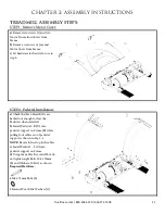
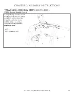
STEP 9
A
Console Mast Assembly
:
a
) Attach the rear console cover (L)
with 3 Screws M4 x 10mm (c) as
shown.
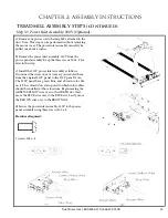
Note: For specific console assembly
instructions, see the corresponding
section at the end of Chapter 2:
Assembly Instructions.
Required Hardware:
3 M4 x 10mm screws (c)
Truefitness.com / 800.426.6570 / 636.272.7100
17
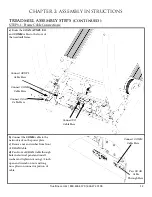
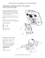
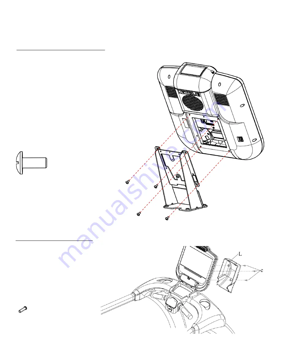
STEP 9
B
Rear Console Cover:
Place the two bottom console mounting screws
inside the bottom keyholes on the console mast
assembly. Partially thread the two top console
mounting screws into the console. Fully tighten all
four console mounting screws.
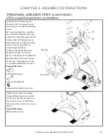
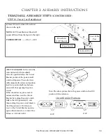
Note: Ensure all cable connections are routed
inside the console mast assembly to prevent cable
pinching.
Note: Refer to the respective console manual
included with your console for wiring connections.
Hardware Required:
Part Number 00567800
Qty 4: M5 x 12 bolts
Summary of Contents for TC400
Page 10: ...CHAPTER 1 SAFETY INSTRUCTIONS Truefitness com 800 426 6570 636 272 7100 6 ...
Page 39: ...CHAPTER 6 ADDITIONAL INFORMATION WIRING DIAGRAMS Truefitness com 800 426 6570 636 272 7100 35 ...
Page 40: ...CHAPTER 6 ADDITIONAL INFORMATION WIRING DIAGRAMS Truefitness com 800 426 6570 636 272 7100 36 ...

