
............ www.truemfg.com ............
............ www.truemfg.com ............
True Food Service Equipment, Inc.
True Food Service Equipment, Inc.
6
6
6
6
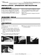
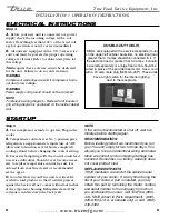
INSTALLATION / OPERATION INSTRUCTIONS
INSTALLATION / OPERATION INSTRUCTIONS
DEFROST TIME CLOCK OPERATION
(Grasslin Timer)
NOTE:
Defrost timer will need to be
set at current time of day
before plugging unit into
power supply. The defrost
times have been set from the
factory. If you want to change
defrost times please read
through the defrost timer
instructions.
RECOMMENDED DEFROST
SETTINGS:
True Manufacturing has factory set your
defrost time clock to a recommended
time and duration defrost scenario. All
TSID and TDBD will require routine
defrost. Your True equipment has been
designed for three defrost periods (6:00
a.m., 2:00 p.m. and 10:00 p.m.). If you
decide to deviate from these defrost
time settings please follow the proce-
dures for adjustment below.
REQUIRED TOOLS:
•
Phillips Screwdriver
•
1/4” Nut Driver or Socket
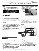
Locating The Defrost Timer:
Take off louvered grill assembly by
removing four (4) corner screws.
TSID and TDBD Models:
Defrost timer is located in the lower
right corner behind the louvered grill
(inside galvanized electrical box).
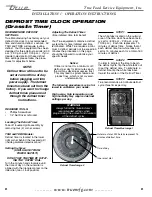
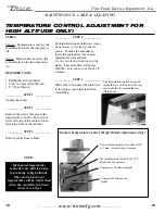
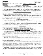
Setting the timer:
(UNPLUG UNIT FROM
POWER SUPPLY!)
DO NOT SET THE TIME BY ROTAT-
ING THE “OUTER” DIAL.
Turn the minute hand clockwise until
the time of day on the outer dial is
aligned with the triangle marker on the
inner dial (two o’clock position).
Adjusting The Defrost Timer:
(time initiated, time terminated)
Your True equipment contains a defrost
system that is time initiated and time
terminated. While True requires a mini-
mum 3 defrost periods not to exceed 60
minutes the procedure on this page
should be followed to customize your
specific needs.
Notice:
If timer is not set for a minimum of 3
defrost per day for 60 minutes each,
the coil may develop excessive frost.
This may lead to system failure and
product loss, which is not covered
under warranty.
The following procedure may be fol-
lowed to customize your needs.
High usage, high temperature, and
high humidity may require 4 defrost
settings per day.
WARNING:
Always follow the manufacturer’s
recommended settings when
programming the amount and duration
of the defrost cycles.
STEP 1
The white tabs located on the outmost
area of the time clock have been facto-
ry set for (6:00 a.m., 2:00 p.m., and
10:00 p.m.). Each tab represents 15
minutes of defrost time. Notice that at
each defrost time four white tabs are
set for 15 minutes each for a total of 60
minutes of defrost.
STEP 2
In order to program the time to begin
the defrost cycle, flip the white tabs out
to set the defrost time. To eliminate a
defrost time flip the white tabs back
toward the center of the Defrost Timer.
STEP 3
True recommends a 60 minute defrost
cycle three times per day.
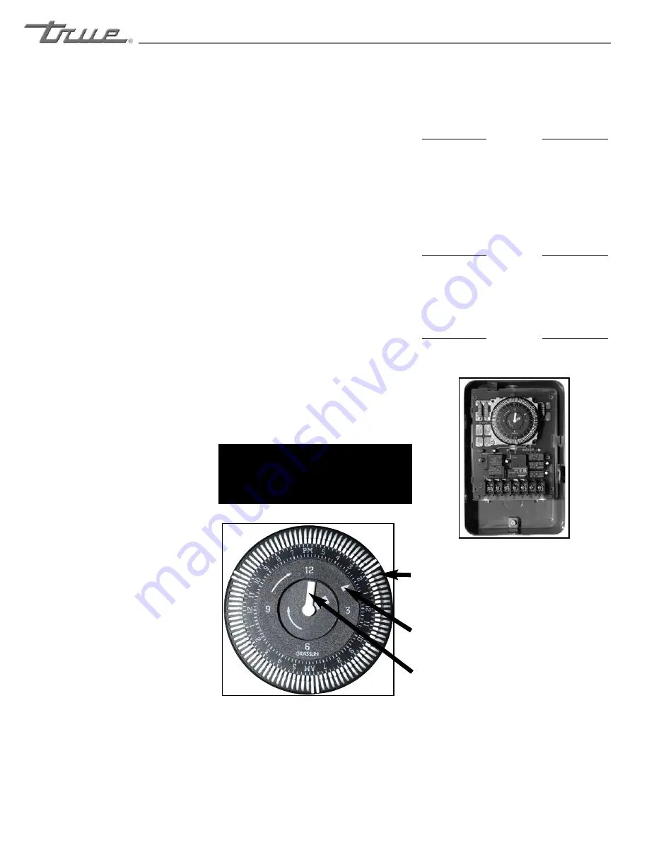
Inner most dial.
Time of day.
Outer most dial. White tabs represent 15
minutes of defrost time.
Defrost Timer Box Image 1
Defrost Timer Image 2


