CHAPTER 2: ASSEMBLY GUIDE
Truefitness.com / 800.426.6570 / 636.272.7100
17 of 34
ASSEMBLY STEPS:
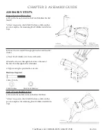
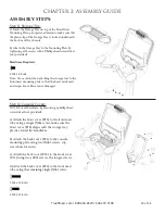
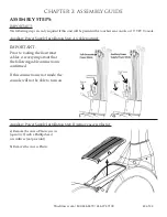
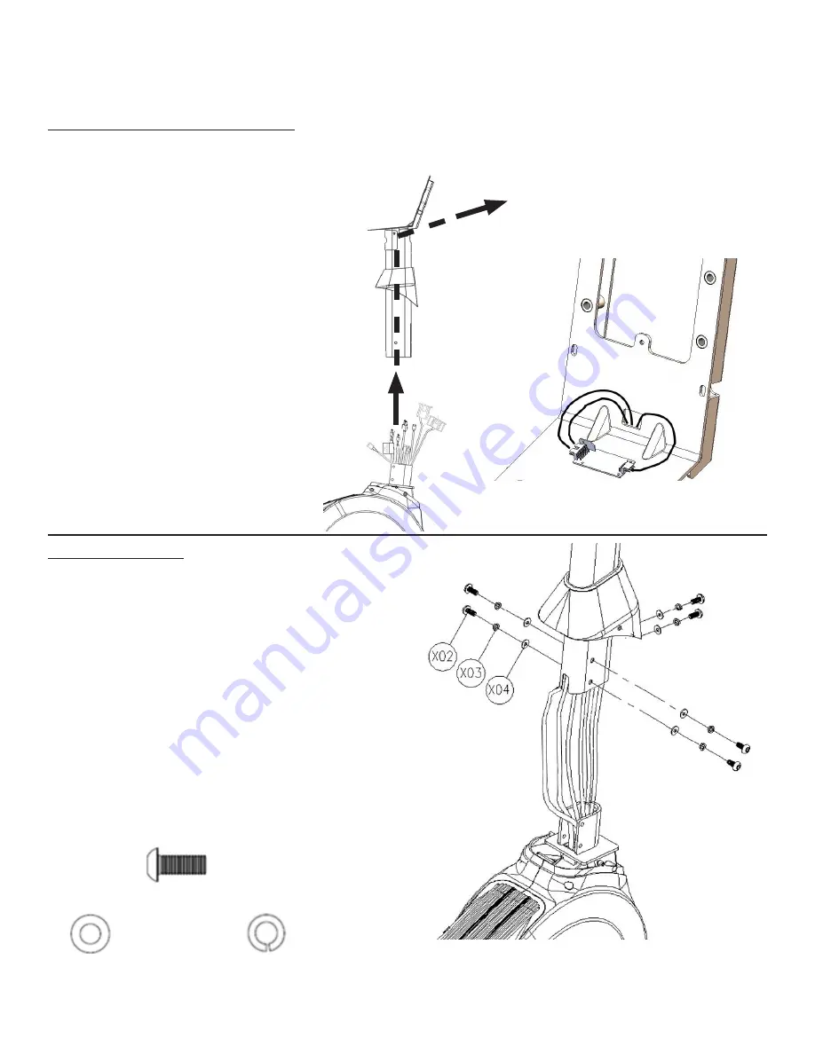
Step 4 Front Mast Cable Routing:
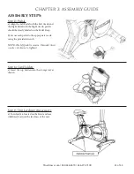
*Complete the power supply installation on page 22 prior to completing this step if this unit will be paired with a
touchscreen or 15” TFT console.
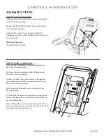
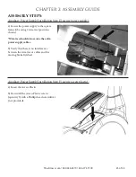
Step 5 Front Mast:
a) For each screw, install through split washer then flat
washer.
b) Insert the Front Mast onto exposed bike frame
U-bracket; pay special attention not to pinch any wires
between the Front Mast and the frame.
c) Verify that the Front Mast is in the correct orientation.
d) Secure the Front Mast to the bike frame by tightening
all 6 screws with the provided hex wrench.
e) Verify that the Front Mast is secured tightly to the
bike frame; tighten screws if necessary.
Hardware Required:
a) Pull the cable bundle coming from the
base of the unit through the front mast
using the pull tie provided with the mast.
Note: The Heart Rate cables are shown
in this step for illustration, but are not
installed until Step 7 (Handlebar Cable
Routing).
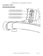
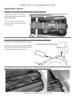
NOTE: This connector is only used for
the touchscreen or 15” TFT console
installation.
If installing a touchscreen or 15” TFT
console, please refer to “Power Supply
Installation, Step A” before proceeding with
“Front Mast Cable Routing, Step 4”.
6 M8 x 20 Bolts
6 M8 Washers
6 M8 Lock Washers
Summary of Contents for UC900
Page 9: ...Truefitness com 800 426 6570 636 272 7100 9 of 34 CHAPTER 1 SAFETY INSTRUCTIONS...
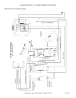
Page 26: ...CHAPTER 2 ASSEMBLY GUIDE Truefitness com 800 426 6570 636 272 7100 26 of 34 WIRING DIAGRAMS...
Page 27: ...CHAPTER 2 ASSEMBLY GUIDE Truefitness com 800 426 6570 636 272 7100 27 of 34 WIRING DIAGRAMS...
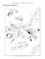
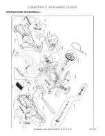
Page 28: ...CHAPTER 2 ASSEMBLY GUIDE Truefitness com 800 426 6570 636 272 7100 28 of 34 EXPLODED DIAGRAM...
Page 29: ...CHAPTER 2 ASSEMBLY GUIDE Truefitness com 800 426 6570 636 272 7100 29 of 34 EXPLODED DIAGRAM...

