CHAPTER 2: ASSEMBLY GUIDE
Truefitness.com / 800.426.6570 / 636.272.7100
19 of 34
ASSEMBLY STEPS:
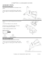
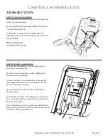
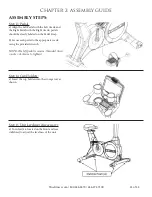
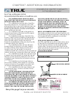
Step 9 Console Mounting:
a) The screws used to attach the Console are provided
in the Console packaging.
b) Align the back of the Console with the Front Mast
Console Mounting Plate.
c) Attach the Console to the Mounting Plate by
tightening all 4 screw with a Phillips head screwdriver
(not provided).
Hardware Required:
*Included with console
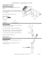
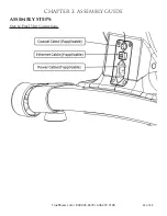
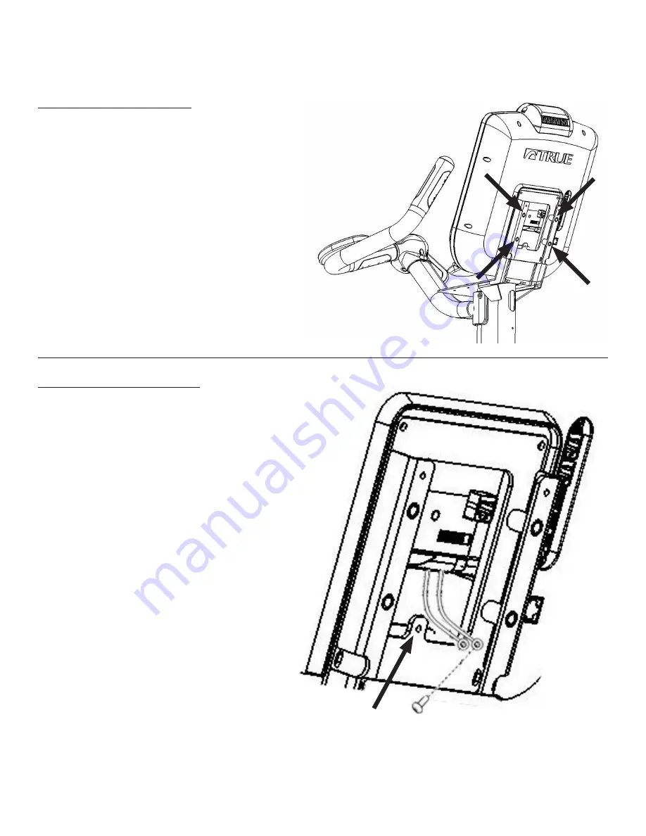
Step 10 Cable Connections:
a) Locate the Ground Screw; pre-installed into the
Front Mast Mounting Plate.
b) Remove the Ground Screw with a Phillips head
screwdriver (not provided).
c) Insert the shaft of the Ground Screw through the
metal rings attached to the console ground wire and
heart rate board ground wire.
d) Re-attach the Ground Screw to the Front Mast
Mounting Plate.
e) Verify that the metal Ground Rings are compressed
between the head of the Ground Screw and the Front
Mast Mounting Plate.
Note: Confirm the console ground wire and the Heart
Rate Board ground wire are both secured to the console
front mast with the ground screw.
Summary of Contents for UC900
Page 9: ...Truefitness com 800 426 6570 636 272 7100 9 of 34 CHAPTER 1 SAFETY INSTRUCTIONS...
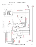
Page 26: ...CHAPTER 2 ASSEMBLY GUIDE Truefitness com 800 426 6570 636 272 7100 26 of 34 WIRING DIAGRAMS...
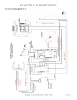
Page 27: ...CHAPTER 2 ASSEMBLY GUIDE Truefitness com 800 426 6570 636 272 7100 27 of 34 WIRING DIAGRAMS...
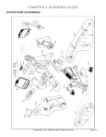
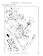
Page 28: ...CHAPTER 2 ASSEMBLY GUIDE Truefitness com 800 426 6570 636 272 7100 28 of 34 EXPLODED DIAGRAM...
Page 29: ...CHAPTER 2 ASSEMBLY GUIDE Truefitness com 800 426 6570 636 272 7100 29 of 34 EXPLODED DIAGRAM...

