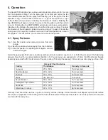
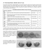


4.8 Apollo HVLP Turbine Properties
Each Apollo Turbine Unit offers the finisher a maximum operating pressure. This pressure is determined by the size and
output of the unit you have selected. The maximum available pressure will have a direct bearing upon the viscosity of
the fluid that you choose to spray. Atomizing pressure and fluid viscosity directly relate to the efficiency of the equipment
operation and the quality of the results that you will achieve. Apollo Models 835VR and 1050VR offer the additional option
to reduce and set atomizing pressure with the variable speed control installed on these units including an accurate pressure
display module.
Model
Turbine Size
Unrestricted Pressure
700, 725
2 Stage
4.5 PSI, 0.31 BAR
800, 825,
3 Stage
5.5 PSI, 0.38 BAR
835, 835VR
3 Stage
7.0 PSI, 0.48 BAR
900
3 Stage
6.0 PSI, 0.41 BAR
10,001,025
4 Stage
8.0 PSI, 0.55 BAR
1035
4 Stage
9.0 PSI, 0.62 BAR
1050, 1050VR
5 Stage
9.5 PSI, 0.70 BAR
1100
2 & 3 Stage
3.5 PSI—10 PSI, 0.24 BAR- 0.69 BAR
1200
2 & 3 Stage
3.5 PSI—10 PSI, 0.24 BAR- 0.69 BAR
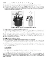
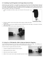
4.9 Cleaning Your 7500 AtomiZer Spray Gun
After you have finished spraying, follow these simple steps to clean your Apollo spray gun:
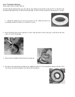
4.9.1 Partial Cleaning
Cleaning your 7500 AtomiZer spray gun does not have to be a difficult task. Often, when spraying a variety of clear coatings,
a thorough rinsing and wiping of basic parts is all that may be necessary. The basic steps below are for simple and easy
cleaning of your Apollo 7500 AtomiZer spray gun.
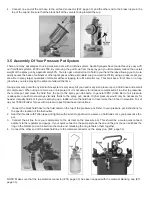
1. Empty any unused material (paint) from the cup and wash out any residue with an appropriate cleaner compatible with
the coating, or water if using water-based material. Partially fill the cup with cleaner and spray through the gun to flush
out the material passages.
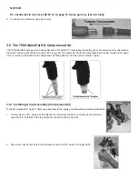
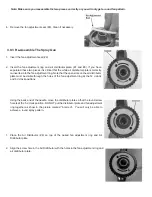
2. Remove the Air Cap (#2) and clean. Ensure that all the air holes in the air cap are clean.
3. Using a brush and solvent, remove any paint deposits on the outer surface of the tip/nozzle (#3). (Apollo FS1900 cleaning
brush kit recommended).
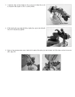
4. Unscrew and remove the Material Adjustment Screw (#19).
5. Remove the needle spring (#20).
6. Pull the trigger and then pull the needle (#21) out through the back of the spray gun.
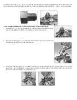
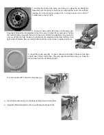
7. Remove the fluid nozzle (#3) with the wrench (spanner) provided.
8. Clean both fluid nozzle and needle assembly using cleaner or water and a brush.
9. Reassemble following the instructions in the next section for thorough cleaning. Make sure to oil the needle spring (#20),
the Air Valve Stem (#14) and the Gland Seal (#24) to prevent the needle from sticking.
10. To adjust the Gland nut (#23) tighten until the needle sticks, then back off the nut about 1/8 turn. Do not over tighten
the gland nut or the needle will stick. Do not under tighten or the Gland Seal will leak.
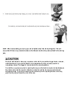
11. Check the Cup Top Gasket and replace if damaged. Always seat the cup top gasket flat in the cup groove. Failure to do
this will allow the cup to drip and impair the spray pattern due to loss of cup pressure.
NOTE:
When
reassembling
your
spray
gun,
do
not
tighten
down
the
Air
Cap
Ring
(#1).
This
will
ensure
that
if
there
is
any
material
residue
on
the
threads
it
will
not
dry
and
seal
itself
to
the
Air
Cap
(#2).
Summary of Contents for Apollo 7500 AtomiZer
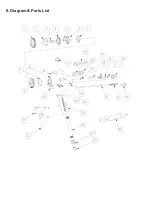
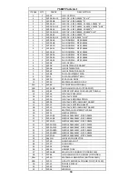
Page 32: ...8 Diagram Parts List...


