


11
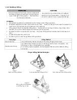
3-5.2 Suction Piping
WARNING
NPSH
A
must always exceed NPSH
R
as shown on TRUFLO
performance curves received with order. (Reference Hydraulic
Institute for NPSH and pipe friction values needed to
evaluate suction piping.
Properly installed suction piping is a necessity for trouble-free pump operation.
Suction piping should be flushed before connection to the pump.
1.
Use of elbows close to the pump suction flange should be avoided. There should be a minimum of 2 pipe
diameters of straight pipe between the elbow and suction inlet. Where used, elbow should be long radius.
2.
Use suction pipe one or two sizes larger than the pump suction, with a reducer at the suction flange. Suction
piping should never be a smaller diameter than the pump suction.
3.
Reducers, if used, should be eccentric, at the pump suction flange, with sloping side down.
4.
Pump must never be throttled on suction side.
5.
Suction strainers, when used, must have net “free area” of at least three times the suction pipe area.
6.
Separate suction lines are recommended when more than one pump is operating from the same source of supply.
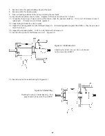
Suction lift conditions
1.
Suction pipe must be free from air pockets.
2.
Suction pipe must slope upwards to pump.
3.
All joints must be airtight and tested
4.
A means of priming the pump must be provided, such as a foot valve.
5.
Piping allowances must be considered to allow air in case and suction piping to vent during priming.
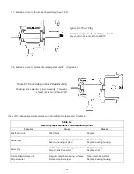
Suction head/Flooded suction conditions
1.
An isolation valve should be installed in the suction line at least two pipe diameters from the suction to permit
closing of the line for pump inspection and maintenance.
2.
Keep suction pipe free from the air pockets.
3.
Piping should be level or slope gradually downward from the source of supply.
4.
No portion of the piping should extend below pump suction flange.
5.
The size of entrance from supply should be one or two sizes larger than the suction pipe.
6.
The suction pipe must be adequately submerged below the liquid surface to prevent vortices and air entrainment
at the supply.
3-5.3 Discharge Piping
Isolation and check valves should be installed in discharge line. Locate the check valve between isolation valve and pump;
this will permit inspection of the check valve. The isolation valve is required for priming, regulation of flow, inspection and
maintenance of pump. The check valve prevents pump from receiving damage due to reverse flow through the pump
when the driver is turned off.
Increasers if used, should be placed between pump and check valves.
Cushioning devices should be used to protect the pump from surge and water hammer if quick-closing valves
are installed in system.


