13
Hose clips SC (part no. 40712-01) are suitable for fastening the pipes
(hoses) to walls or the floor. These hose clips also make it possible to
route water pipes (hoses) on the heater‘s warm
-air distribution pipes
as a way to avoid the danger of frosting.
A water pipe (hose) may only be fitted at a clearance of 1.5 m to the
heater on the warm air duct. The Truma hose clip SC can be used if
this distance is observed. In the case of parallel installations, e.g.
openings through a wall, a spacer element should also be attached
(e.g. insulation) to prevent contact.
Connect cold water supply (23) to safety/drain valve (24). To
guarantee the correct function of the safety/drain valve, the water
pipes/hoses need to be installed without tension!
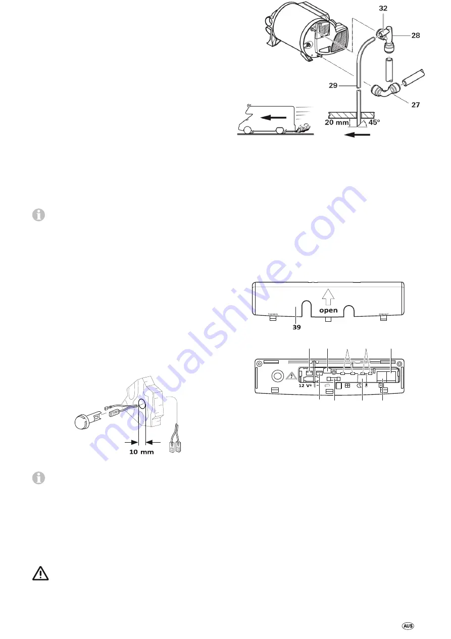
Fig. 25
The elbow fitting (28
–
with aeration valve) is inserted into the upper
warm water connection and the second elbow fitting (27) is inserted
in the lower cold water connection of the heater up to the stop. Pull
in opposite direction in order to make sure the elbow fittings are
securely attached.
Create a pipe/hose connection (25) for the cold water supply
between the safety/drain valve (24) and the boiler intake.
Ensure that the cold water supply does not come into contact
with cold bridges (e.g. the outer wall) in order to
prevent freezing.
Route the hot water supply (26) from the elbow connec tion with
integrated vent valve (28) to the hot water consumers.
Push the venting hose, external diameter 11 mm (29), onto the hose
grommet of the venting valve (28a), and lay it to the outside without
any kinks. Ensure that the bend radius is not smaller than 40 mm.
Cut off the aeration hose about 20 mm below the vehicle floor at a
45° angle to the direction of travel (see figure 25).
Installing the room temperature sensor
When selecting the location, bear in mind that the room
temperature sensor must not be subjected to any direct radiant
heat. For optimum room temperature regulation, we recommend
that the room temperature sensor be fitted above the entrance
door.
Fig. 26
Please ensure that the room temperature sensor is always
attached to a
vertical
wall. There may be no ob-
structions preventing the room air from flowing around it.
Drill a hole 10 mm in diameter. Guide the connection cable through
the drillhole from behind and plug the cable end to the sensor by
means of an insulated connector plug (there is no need to be
concerned about polarity). Slide in the room temperature sensor
and lay the cable end with the two insulated connector plugs to the
electronic control unit (extend to a maximum overall length of 10
m using 2 x 0.5 mm² cable if necessary). connected, otherwise the
heater will switch to fault.
The provided room temperature sensor
must always be
Installing the control panel
The installation of the control panel is described in the instructions
included with the control panel.
Electrical connections
Route connecting cables in such a way that they cannot chafe.
Please also use leadthrough bushings or edge protection profiles
where there are sharp edges such as metal panel leadthroughs. The
connecting cables must not be attached to or come into contact
with metal surfaces, the exhaust duct or warm air ducts.
The electrical connections are located under the connection cover
(39). The cover can be removed by pressing and simultaneously
sliding it in the direction of the arrow. When removing or
installing the connection cover on the connection cables, make
sure that the cables are not pulled out or become pinched.
40
42
44
46
48
41
43
45
47
Fig. 27
40 = Input v12 V (spade connector 6.3 mm) 41 =
Input voltage -12 V (spade connector 6.3 mm)
42
= not used
43
= Device fuse: 10 A
–
slow
–
(T 10 A)
44
= Wire bridge (or window switch
–
accessory)
45
= not used
46
= Room temperature sensor
47
= Control panel / Diagnostic connector*
48
= Control panel / Diagnostic connector*
* Alternative connections.
All connections to the unit should be made with sagging connection
cables. This will prevent condensation water from running down the
connection cables and into the unit.


