22
7200790 Service Manual for the HELION
®
XENION
®
Surgical Lighting System GB
6 Setting the Luminous Field
6.3
6.3
6.3
6.3
6.3
Setting the luminous field for the XENI-
Setting the luminous field for the XENI-
Setting the luminous field for the XENI-
Setting the luminous field for the XENI-
Setting the luminous field for the XENI-
ON L/L+
ON L/L+
ON L/L+
ON L/L+
ON L/L+
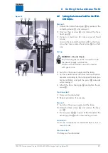
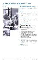
Removal:
1. Unlock the central hand grip
2
by means of the
unlocking device
1
and remove it.
2. Unscrew the four cross-recessed head screws
6
and remove the trim ring
3
.
3. Set the maximum and minimum luminous field
diameters on the two cross-recessed head screws
according to the lamp specification
4
/
5
.
Functional test:
4. Carry out functional test.
5. Repeat procedure if necessary.
6. Fix the cross-recessed head screws
4
/
5
with
screw-locking varnish.
Installation:
7. Fit the components as described above, but in
reverse order.
6.4
6.4
6.4
6.4
6.4
Setting the luminous field for the XENI-
Setting the luminous field for the XENI-
Setting the luminous field for the XENI-
Setting the luminous field for the XENI-
Setting the luminous field for the XENI-
ON M with fixed focus camera
ON M with fixed focus camera
ON M with fixed focus camera
ON M with fixed focus camera
ON M with fixed focus camera
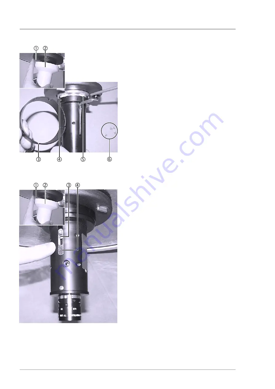
Removal:
1. Unlock the central hand grip
2
by means of the
unlocking device
1
and remove it.
2. Unscrew the cross-recessed head screw
3
.
3. Set the maximum and minimum luminous field
diameters according to the lamp specification by
adjusting the ribbed surface
4
.
4. Tighten the cross-recessed head screw
3
.
Functional test:
5. Carry out functional test.
6. Repeat procedure if necessary.
7. Fix the cross-recessed head screw
3
with screw-
locking varnish.
Installation:
8. Fit the components as described above, but in
reverse order.
Figure 03
Figure 04


