30
7200790 Service Manual for the HELION
®
XENION
®
Surgical Lighting System GB
Figure 04
10.5
10.5
10.5
10.5
10.5 Dismantling the spring arm
Dismantling the spring arm
Dismantling the spring arm
Dismantling the spring arm
Dismantling the spring arm
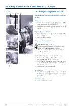
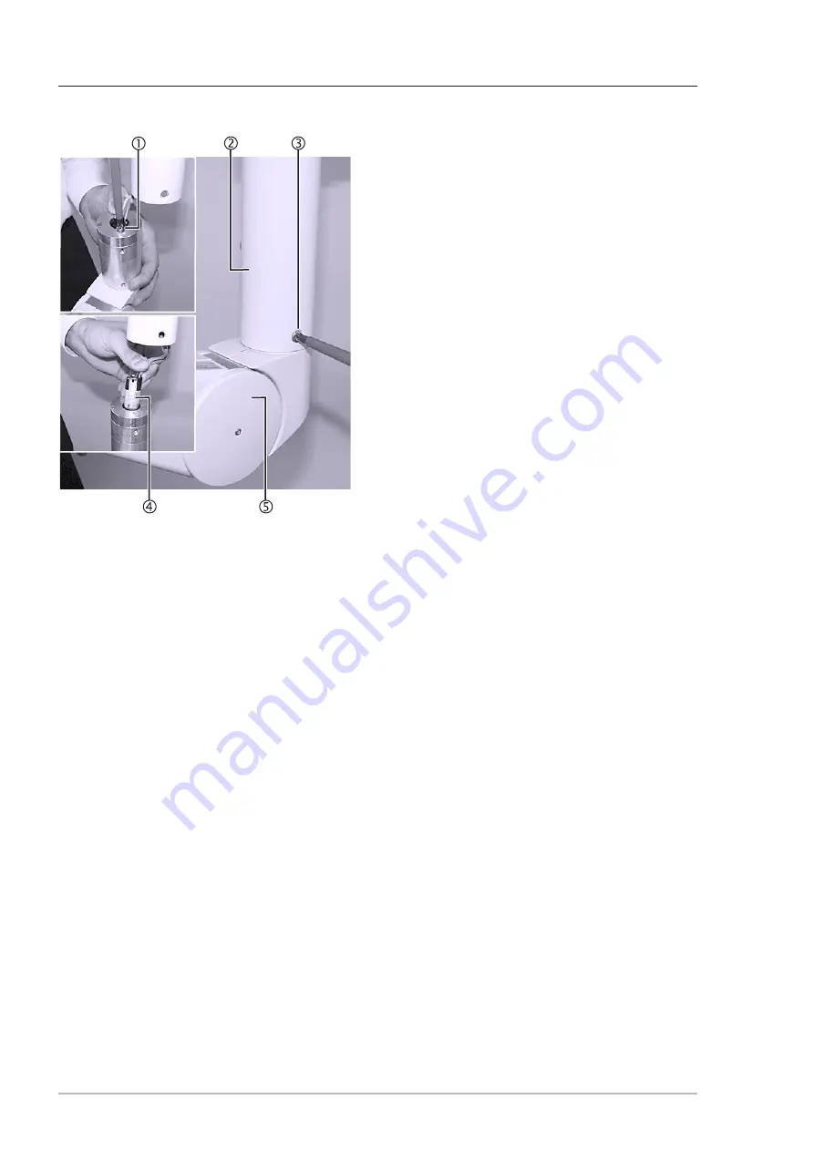
1. Unscrew the four recessed countersunk head
screws M5 x 8 mm
3
.
2. Carefully remove the spring arm
5
from the ex-
tension tube
2
.
Only if there are additional cables in the spring
arm:
3. Remove the lateral covering on the spring arm.
4. Undo the cable fixtures and carefully remove the
cables from the spring arm.
5. Unscrew the two cross-recessed head screws
1
and carefully remove the plug-in connector
4
from the spring arm
5
.
6. Carefully put the spring arm
5
aside.
10.6
10.6
10.6
10.6
10.6 TTTTTesting the cables in the extension arm
esting the cables in the extension arm
esting the cables in the extension arm
esting the cables in the extension arm
esting the cables in the extension arm
1. Carry out an all-pole contact resistance test bet-
ween the extension arm (sliding connector) and
the contact block in the extension arm:
•
If the resistance is infinite, the cables in the exten-
sion arm must be replaced in accordance with
Section 10.7.
• If the resistance is almost zero, the cables in the
spring arm must be tested:
- Carry out an all-pole contact resistance test bet-
ween the two sliding couplings of the spring arm
(replace the entire cabled spring arm if necessa-
ry).
10 Testing the Electrics of the Support System

