Connection cables carry life-threatening voltage.
Ø
Do not work under voltage.
Ø
Before connecting, check DC link voltage cables to ensure
that they are not electrically live.
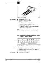
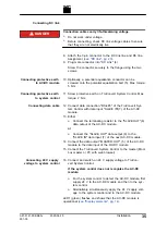
8. Attach the 3-pin connector to the DC link line and PE line.
Assignment
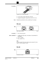
9. Plug male connector into "DC Link" (4).
Screw the connector securely to the flange using the two
screws.
10. Optionally, a potential equalization conductor can be
screwed onto the potential equalization bolt (5). Max. torque:
5 Nm.
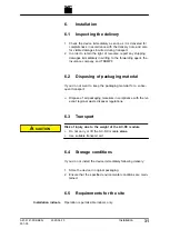
11. Screw protective earth on TruConvert System Control. Max.
torque: 2 Nm.
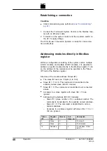
12. Connect data connection "RS-485" of the TruConvert Sys-
tem Control with data input "SLAVE IN"(7) of the AC-DC
module.
13. Either
Ø
Connect the terminating resistor to the "SLAVE OUT"(8)
data output of the AC-DC module.
or
Ø
Connect the "SLAVE OUT" data output (8) to the
"SLAVE IN" data input (7) of the next AC-DC module.
14. Connect the data output "MASTER OUT" (5) of the AC-DC
module to the data input of the DC-DC module.
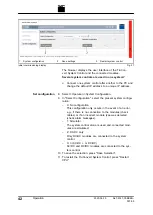
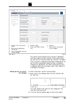
15. Connect the TruConvert System Control to the master (Mod-
bus master or PC with web browser)
16. Connect and switch on 24 V supply voltage to TruCon-
vert System Control.
If the system control does not recognize the AC-DC
module:
Ø
For the system control to detect the AC-DC module, first
supply 24 V to the AC-DC module and then to the sys-
tem control.
Ø
Alternatively, simultaneously apply the 24 V supply volt-
age to the system control and to the AC-DC module.
LED1 (green) flashes and shows that the AC-DC module is
operational
(see "Display elements", pg. 14)
.
A67-0141-00.BKEN-
001-05
2020-06-10
Installation
35
Connecting DC link
DANGER
Connecting protective earth
to AC-DC module
Connecting protective earth
to system control
Connecting data cable
Connecting 24 V supply
voltage to system control


