background image


6


6.3 Grounding 

Trunsun Solar modules use an anodic oxidized 

aluminum frame to resist corrosion. So the 

frame of modules must be connected to the 

equipment grounding conductor to prevent 

thunder and static injury. The grounding device 

must be fully contact with the inside of the 

aluminum alloy, and must penetrate the surface 

of the frame oxidation film. 

Please don’t drill any additional grounding hole 

on the frame of the modules. 

For optimal performance, Trunsun Solar 

recommend the DC cathode of the modules 

array is connected to ground. Failure to comply 

whit this requirement may reduce the 

performance of the system. 

The grounding method must not result in direct 

contact of dissimilar metals with the aluminum 

frame of the modules that will result in galvanic 

corrosion. An addendum to UL standard 1703 

“Flat Plate Photovoltaic Modules and Panels” 

recommends metal combinations not exceed 

electrochemical potential difference of 0.6 volts. 

The frame rails have pre-drilled holes marked 

with      is a grounding sing. These holes should 

be used for grounding purpose and must not be 

used for mounting the modules. The following 

grounding methods are available. 

There is a grounding hole 4.0mm diameter on 

the edge side closer to the middle of the back 

frame of module. All module frames should be 

grounded for safety. The grounding 

connections between modules must be 

approved by a qualified electrician, the 

grounding itself must be made by a qualified 

electrician. The grounding clip accepts solid 

uninsulated copper wire sizes 12 AWG. The 

wire must not be nicked. 

The module shall wire in accordance with the 

standard, the grounding method of the frame of 

arrays shall comply with IEC 61215. Of course, 

in accordance with local laws and regulations to 

carry out electrical installation is the best 

choice. 

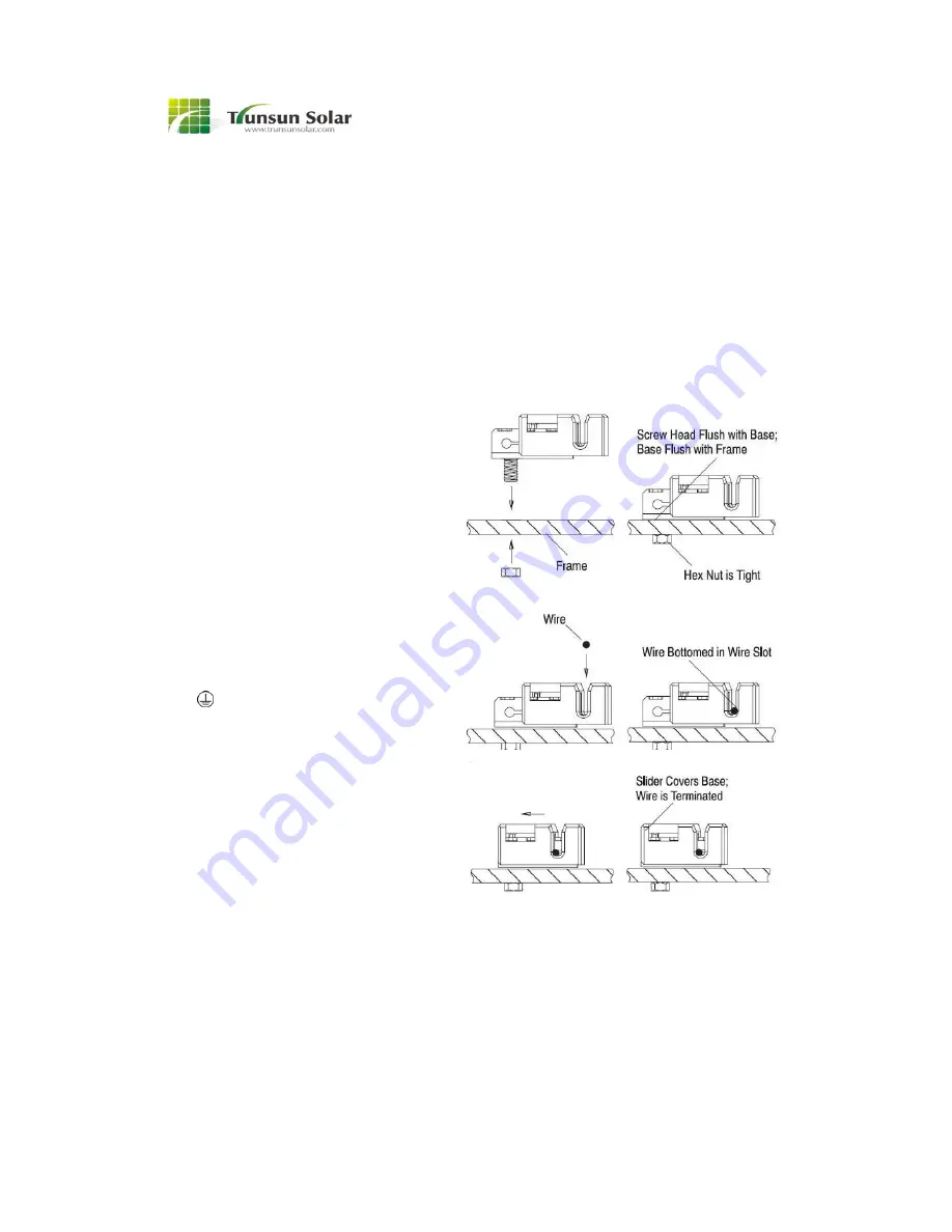
Use the UL listed grounding clip manufactured 

by Tyco Electronics Corp with type name 

1954381-2. Place the grounding clip onto the 

module frame so that the screw straddles the 

grounding hole, then tighten the screw and nut 

with a torque 2.3 to 2.8 Nm. The head of the 

screw must be flush with the base and the base 

must be flush with the frame. The copper wire 

should not be compressed during the 

installation. 

Place a 12 AWG copper wire in the wire slot 

then engage the slider. Detailed process is as 

the following: 

Figure 4 


Trunsun solar modules can be grounded using 

third party grounding devices so long as the are 

certified for grounding modules and the devices 

are installed according to the manufactures’s 

specified instructions. 

6.4 Wiring 

Modules are equipped with factory installed 

wires and quick connectors. Modules have 

been designed to be easily interconnected in 

series.  

Bolt diameter is 
4mm.

Summary of Contents for TSM175-72

Page 1: ...ificially concentrate sunlight onto the modules 2 INTRODUCTIONS TRUNSUN SOLAR modules come in various sizes to satisfy a full range of applications Each module is made of crystalline silicon cells To...

Page 2: ...essures greater than 112 9pounds per square foot 551Kg m2 of uniformly distributed wind snow or other loading The modules have been tested by TUV for a maximum front loading of 5400Pa backside loading...

Page 3: ...cture using 8 holes for normal installation as indicated in figure 1 Load calculations shall be done by the system designer or installer Each hole shall be installed in the order as in the following f...

Page 4: ...ion required to mount the module must be properly sealed to prevent leaks 5 In some cases a special support frame may be necessary 6 The roof installation of solar modules may affect the fireproofing...

Page 5: ...g and support frames suitable for use in a solar electric system Always use the same type of module within a particular photovoltaic system 6 ELECTRICAL INSTALLAIONS 6 1 Bypass diodes Modules contain...

Page 6: ...ame of module All module frames should be grounded for safety The grounding connections between modules must be approved by a qualified electrician the grounding itself must be made by a qualified ele...

Page 7: ...er additional wires with pre attached connectors may be used The wire shall be PV wire or USE 2 wire the connectors shall be manufactured by Multi Contact USA with model type PV KBT4 6II UR female and...

Page 8: ...to as little as 5 of full sunlight and both current and power increase with light intensity Do not touch live parts of cables and connectors As an additional precaution use insulated tools and rubber...

Page 9: ...talled by the manufacturer Do not treat the back of the module with paint or adhesives If not otherwise specified it is recommended that requirements of the latest local national or regional electrica...

Page 10: ...crystalline silicon PV module TSMxxx 72 NOTE TSM 72 Electrical Specification and Mechanical Specification can be found in the last page Electrical Specification and Mechanical Specification D C down...

Page 11: ...crystalline silicon PV module TSPxxx 54 NOTE TSP 54 Electrical Specification and Mechanical Specification can be found in the last page Electrical Specification and Mechanical Specification D C down...

Page 12: ...crystalline silicon PV module TSMxxx 60 NOTE TSM 60 Electrical Specification and Mechanical Specification can be found in the last page Electrical Specification and Mechanical Specification D C down...

Page 13: ...crystalline silicon PV module TSMxxx 60 NOTE TSM 60 Electrical Specification and Mechanical Specification can be found in the last page Electrical Specification and Mechanical Specification D C down...

Page 14: ...crystalline silicon PV module TSPxxx 60 NOTE TSP 60 Electrical Specification and Mechanical Specification can be found in the last page Electrical Specification and Mechanical Specification D C down...

Page 15: ...crystalline silicon PV module TSPxxx 60 NOTE TSP 60 Electrical Specification and Mechanical Specification can be found in the last page Electrical Specification and Mechanical Specification D C down...

Page 16: ...crystalline silicon PV module TSMxxx 72 NOTE TSM 72 Electrical Specification and Mechanical Specification can be found in the last page Electrical Specification and Mechanical Specification D C down...

Page 17: ...crystalline silicon PV module TSMxxx 72 NOTE TSM 72 Electrical Specification and Mechanical Specification can be found in the last page Electrical Specification and Mechanical Specification D C down...

Page 18: ...crystalline silicon PV module TSPxxx 72 NOTE TSP 72 Electrical Specification and Mechanical Specification can be found in the last page Electrical Specification and Mechanical Specification D C down...

Page 19: ...crystalline silicon PV module TSPxxx 72 NOTE TSP 72 Electrical Specification and Mechanical Specification can be found in the last page Electrical Specification and Mechanical Specification D C down...

Page 20: ...4 6 9 17 5 1480 991 50 35 195 1000 30 80 8 50 25 70 7 59 13 3 A C 15 32 1 TSP200 54 Poly 54 6 9 17 5 1480 991 50 35 200 1000 31 30 8 58 26 10 7 66 13 6 A C 15 31 1 TSP205 54 Poly 54 6 9 17 5 1480 991...

Page 21: ...5 25 1 TSM275 60 Mono 60 6 10 18 5 1650 991 40 28 275 1000 39 36 9 09 32 55 8 45 16 8 A C 15 25 1 TSM280 60 Mono 60 6 10 18 5 1650 991 40 28 280 1000 39 48 9 21 32 72 8 56 17 1 A C 15 25 1 TSM285 60 M...

Page 22: ...5 21 1 TSM300 72 Mono 72 6 12 22 5 1956 991 45 35 300 1000 46 55 8 53 37 65 7 97 15 5 A C 15 21 1 TSM305 72 Mono 72 6 12 22 5 1956 991 45 35 305 1000 46 68 8 62 37 89 8 05 15 7 A C 15 21 1 TSM310 72 M...

Page 23: ...21 1 TSP315 72 Poly 72 6 12 22 5 1956 991 45 35 315 1000 46 58 8 81 37 91 8 31 16 3 A C 15 21 1 TSP320 72 Poly 72 6 12 22 5 1956 991 45 35 320 1000 46 72 8 89 38 19 8 38 16 5 A C 15 21 1 TSP325 72 Po...

Reviews: