background image

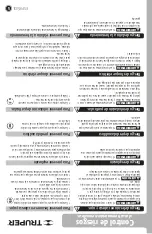
Turning ON

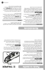
• Turn on the air compressor and allow it to fill.

• Regulate the air compressor output pressure from 517 kPa 

to 758 kPa (75 PSI to 110 PSI).


                    The tool operates at this pressure range; 

operating at higher pressure ranges will result in shorter tool 

life.

• Slide the trigger lock to the front and then with a full palm 

press the trigger to start the grinder spinning.

• Release the trigger to stop the grinder.

• Check that the workpiece is properly clamped. It should be 

held in such a way that throughout the cut, the groove made 

by the blade maintains or increases its width.

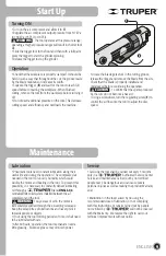
• Squeeze the trigger (

E

) and wait for the tool to reach full 

speed before contacting the workpiece. When finished 

cutting, remove the tool from the workpiece before turning it 

off.

• Do not exert additional pressure on the tool. This decrease 

cutting speed and efficiency and overloads the machine.

• In case the blade gets stuck in the cutting groove, 

release the trigger and remove the blade from the site.  

Check that the blade is properly installed and 

undamaged before continuing the operation.

                            • Confirm that the sparks produced 

by the cuts do not become a hazard.

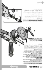
• Using a screwdriver, turn the regulating screw (

F

) to 

control the air flow into the tool to adjust the disc 

speed.

9

Start Up

Maintenance

E

F

Operation

CAUTION

WARNING

• Pneumatic tools need constant lubrication along their 

useful life and during the operation. The compressed air 

needed in the tool to run carry humidity which could 

oxidize the motor and bearing in the tool.  To prevent this 

possibility, it is necessary to constantly deliver lubricating 

oil through a                                 Brand 

UNI-LL-1/4


centralized filter-oiler system installed between the air 

compressor and the tool.

                             • Any excess of oil in the motor is 

immediately expelled through the exceeding oil escape. 

Keep the escape free of obstructions and never point it 

towards people or objects.

• If not using the tool for long periods of time, it shall need 

to be lubricated with care.

• After 60 hours’ operation, the tool mechanism need a 

little greasing.  Excessive grease may diminish power.

• Servicing the tool shall be carried out every 3 months 

only in a                                 Authorized Service Center. 

Service and maintenance carried out by not certified 

people mat y be dangerous and can cause severe 

personal injuries as well as making the product Warranty 

void.

• Malfunction in the tool caused by no using the 

recommended dose of lubrication, or not complying 

with this Instructions, or repairs carried out by people 

not certified by                                 will not be covered 

with the Warranty.  We reserve the right to carry out 

technical improvements without notice.

Lubrication

Service

WARNING

ENGLISH

Summary of Contents for 101072

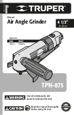
Page 1: ...gle Grinder TPN 875 Model Code TPN 875 Applies for 101072 Disc diameter 4 1 2 Use oil continuously and dosed to lubricate the tool WARNING CAUTION Read this manual thoroughly before using the tool ENG...

Page 2: ...Warranty Policy 3 3 4 5 7 7 9 9 10 11 12 TPN 875 Contents CAUTION Keep this manual for future references The illustrations in this manual are for reference only They might be different from the real t...

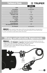
Page 3: ...res lubrication reducing 80 oil consumption significantly increasing the breathing air quality for the operator The filter oil feeder system must be regulated to administer 3 to 6 drops per minute Dra...

Page 4: ...severe personal injuries or crushing Wear adequate protective safety accessories Wear eye protection dust mask non skid safety shoes helmet and ear plugs In normal conditions the risk of injury is red...

Page 5: ...s Pneumatic tools do not have electric insulation If during the operation the tool makes contact with a source of electricity the energy will be conducted to the operator causing a fatal electrocution...

Page 6: ...rp or abrasive edges Unplug the hose when setting up accessories like grinding discs or bits Never use the hose to carry the tool Never pull the hose to unplug it Do not expose the hose to heat oil or...

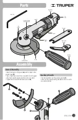
Page 7: ...he holes in the guard A with the holes in the grinder head B Use at least three sets of hex screws C to fix the guard in the most suitable position for the work to be done Tighten the screws with the...

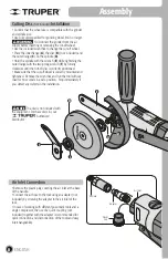
Page 8: ...g Disc Not Included Installation Confirm that the wheel size is compatible with the grinder and spindle size Use only discs specified for grinding wheel r min or larger Disconnect the grinder from the...

Page 9: ...l to adjust the disc speed 9 Start Up Maintenance E F Operation CAUTION WARNING Pneumatic tools need constant lubrication along their useful life and during the operation The compressed air needed in...

Page 10: ...Notes 10 ENGLISH...

Page 11: ...LAJOMULCO DE ZU IGA JAL TEL 33 3606 5285 AL 90 FIX FERRETER AS AV PASEO DE LA REP BLICA 3140 A COL EX HACIENDA DE LA HUERTA C P 58050 MORELIA MICH TEL 443 334 6858 FIX FERRETER AS CAPIT N ANZURES 95 E...

Page 12: ...Corregidora 22 Col Centro Alc Cuauht moc CDMX C P 06060 or at the establishment where you purchased it or at any Truper Service Center listed in the annex to the warranty policy and or in www truper...

Page 13: ...orregidora 22 Col Centro Alc Cuauht moc CDMX C P 06060 o en el establecimiento donde lo compr o en alg n Centro de Servicio Truper de los enlistados en el anexo de la p liza de garant a y o en www tru...

Page 14: ...DE SERVICIO ECLIPSE CALLE PRINCIPAL MZ 1 LT 1 COL SANTA FE C P 39010 CHILPANCINGO GRO TEL 747 478 5793 FERREPRECIOS S A DE C V LIBERTAD ORIENTE 304 LOCAL 30 INTERIOR DE PASAJE ROBLEDO COL CENTRO C P 4...

Page 15: ...Notas 10 ESPA OL...

Page 16: ...la herramienta se deber engrasar un poco El exceso de grasa puede disminuir la potencia Lubricaci n Servicio Encendido Encienda el compresor de aire y permita que se llene Regule la presi n de salida...

Page 17: ...de corte no incluido Confirme que las medidas del disco sean compatibles con el esmeril y con la medida del husillo Utilice nicamente discos especificados para las r min del esmeril o mayores Descone...

Page 18: ...s orificios de la guarda A con los orificios del cabezal de la esmeriladora B Utilice al menos tres juegos de tornillos hexagonales C para fijar la guarda en la posici n m s adecuada para el trabajo a...

Page 19: ...ejada se superficies afiladas o abrasivas Desconecte la manguera cuando instale accesorios como discos de esmeril o brocas Nunca use la manguera para cargar la herramienta Nunca jale de la manguera pa...

Page 20: ...i n de part culas Las herramientas neum ticas no cuentan con aislamiento el ctrico Si durante su operaci n llegan a hacer contacto con alguna fuente de electricidad conducir la energ a al operador pro...

Page 21: ...lla antipolvo zapatos de seguridad antideslizantes casco y protecci n para los o dos en condiciones adecuadas reducen considerablemente el riesgo de lesiones Desconecte la manguera de aire de la herra...

Page 22: ...mento en la presi n de l nea o el di metro interior de la manguera para compensar el uso de mangueras muy largas m s de 8 metros El di metro interior m nimo de la manguera debe ser de 3 8 9 5 mm y los...

Page 23: ...rizados P liza de Garant a Guarde este Instructivo para futuras referencias Los gr ficos de este Instructivo son para referencia pueden variar del aspecto real de la herramienta 3 3 4 5 7 7 9 9 10 11...

Page 24: ...ada para lubricar la herramienta Esmeriladora angular neum tica TPN 875 Modelo C digo TPN 875 Este Instructivo es para 101072 115 mm Di metro de disco 4 1 2 ADVERTENCIA ATENCI N Lea este Instructivo p...

Reviews: