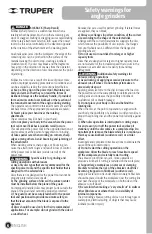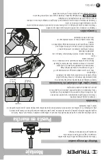
Parts
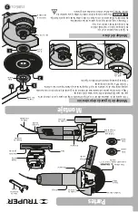
Auxiliary
handle
4
1
/
2
” abrasive
disc included
Axis
lock
Inner
flange
Outer
flange
Axis
lock
Vent
slots
Auxiliary handle
assembling orifice
Protective
guard
Protective
guard
Switch
Switch
Lock nut wrench
(Included)
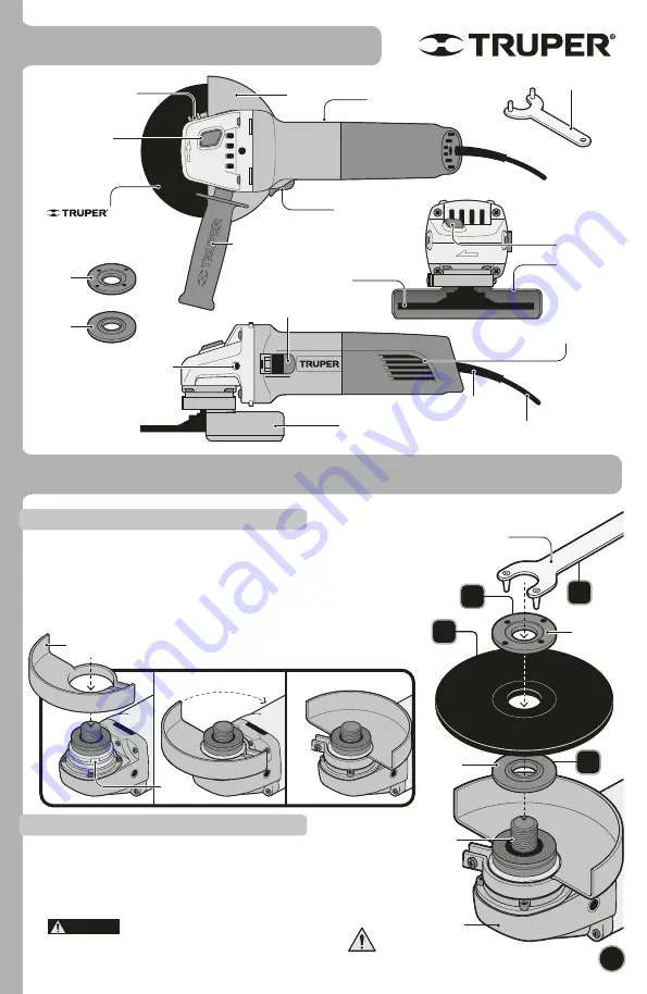
Assembly
7
ENGLISH
1
Protective
guard
Lock nut
wrench
Inner
flange
5/8-11-UNC-1A
Grinder
head
Outer
flange
Slot
Disc
1.
Fit the inner flange onto the axis.
2.
Set the disc onto the inner flange.
3.
Set the outer flange onto the axis.
• Press the axis lock into the grinder head.
4.
Screw the outer flange with the lock nut wrench until securely fastened.
The axis lock should only be used to change discs.
Never use the wrench to stop the disc while rotating.
Disc Assembly
Protection Guard Assembly
2
3
4
DANGER
Power
supply cable
Power cord
protector
Protective
guard
Handle
• Using a philips screw, loosen the fixing screw so that the inner side of the guard
passes freely over the slots on the cover.
• Match both cantilevered parts inside the protection guard with the corresponding
slots in the axis cover. Push down to the cover.
• Turn 180° into the opposite position.
• Fix guard by tightening the fixing screw.
Fixing screw
4
1
/
2
” abrasive
disc included
model ABT-386
Summary of Contents for 101526
Page 10: ...10 ENGLISH Notes...
Page 15: ...10 Notas ESPA OL...


