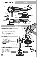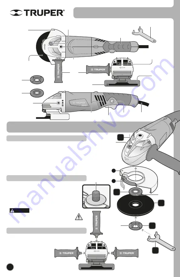
Parts
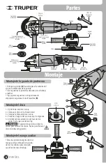
Auxiliary
handle
Abrasive disc
4
1
/
2
” included
Protective
guard
Axis
lock
Inner
flange
Outer
flange
Axis
lock
Continuous
use button
Auxiliary handle
assembling orifice
Auxiliary handle
assembling orifice
Vent
slots
Protective
guard
Switch
Handle
Two pin
spanner wrench
(Included)
Abrasive disc
4
1
/
2
” included
Power
supply cable
6
ENGLISH
Assembly
5
2
Axis
lock
Outer
flange
Inner
flange
Disc
• For a safe operation use the
auxiliary handle. Fit the auxiliary
handle onto one of the three
mounting orifices to make the job
easier.
Auxiliary handle assembly
3
4
1
A
B
• Install guard (
A
) passing the axis cover through the
guard clamp.
• Turn the guard onto the position adequate for the
job.
• Fix and fasten guard onto the desired place by
pushing the clamp lever (
B
).
Protection guard assembly
1.- Fix the inner flange into the axis.
2.- Set the disc into the inner flange.
3.- Set the outer flange in the axis.
4.- Press the axis lock in the gearbox.
5.- Screw the outer flange using the two-pin spanner
wrench until perfectly fixed.
The axis lock should only be used
to replace discs. It shall never be used to stop the
disc while rotating.
Disc assembly
DANGER
5/8-11
UNC-1A
Summary of Contents for 16441
Page 9: ...9 Notas ESPA OL...
Page 21: ...9 ENGLISH Notes...

