background image

9

Chapter 4:
Operation & Maintenance

4.1 How to operate the UPS

1. Switch on

Press and hold the on/off/test/silence button for more than 1
second until the Energy Normal LED is lit. The UPS will
perform a self-test each time it is switched on.

2. Switch off

Press and hold the on/off/test/silence button for more than 1
second until the Energy Normal or Backup LED goes out.

3. Self-Test

Use the self-test function to verify both the operation of the
UPS and the condition of the battery. When the UPS is
switched on, press the on/off/test/silence button for less
than 1 second. The UPS will immediately start the self-test.
During the self-test, the UPS operates in the Backup mode
and will go back to the Energy Normal mode as soon as the
self-test is finished.

4. Silence

Use this function to silence the alarm. When the UPS is in
the Backup mode, press the on/off/test/silence button for
less than 1 second.

Note
This function does not work when the UPS has a Low Battery or Overload
status.
If you are using the UPSMON software, you can set the UPS to turn off
automatically during the Backup mode, if none of the connected devices
is operating.

Summary of Contents for Energy Protector 325

Page 1: ...Trust Energy Protector 325 525 User s Manual...

Page 2: ...nties of merchantability and fitness for a particular purpose with respect to the software the product manual s and written materials and any other accompanying hardware The manufacturer reserves the...

Page 3: ...ions 1 Chapter 2 System Description 3 Chapter 3 Setup 7 Chapter 4 Operation Maintenance 9 4 1 How to operate the UPS 9 4 2 How to maintain the UPS 10 Chapter 5 Software 525 11 Chapter 6 Troubleshootin...

Page 4: ...25 including an on line voltage boost up and buck down The Trust Energy Protector is based on microprocessor controls This means that it operates as soon as the utility power is connected so there is...

Page 5: ...e high voltage even if the unit is not powered on When the fuse has blown replace it only with a fuse of the same type to reduce the risk of fire The battery should only be serviced by experienced per...

Page 6: ...2...

Page 7: ...attery indicator red LED The LED illuminates when the UPS s battery needs to be replaced Note When replacing the battery disconnect the power cord before opening the cover Be aware of the battery s po...

Page 8: ...s than 1 second to activate the self test or silence the backup alarm 5 Backup mode slow alarm In this mode the yellow LED illuminates and the UPS sounds an audible alarm The alarm stops when the UPS...

Page 9: ...gure 2 Rear panel 1 Computer Interface 525 The interface provides a RS 232 serial connection and a relay signal to support Novell Unix Windows DOS and other operation systems 2 Power output 3 Power in...

Page 10: ...6...

Page 11: ...he UPS in a protected area with adequate air flow and free of excessive dust Do not put the UPS in an area with extreme temperatures or humidity 2 Connecting Computer Interface Optional UPSMON or othe...

Page 12: ...e battery The UPS charges its battery whenever it is connected to the mains For best results charge the battery for 4 hours when you use the UPS for the first time 5 Connecting devices Use the supplie...

Page 13: ...of the battery When the UPS is switched on press the on off test silence button for less than 1 second The UPS will immediately start the self test During the self test the UPS operates in the Backup...

Page 14: ...a little maintenance is required Please pay attention to a few helpful instructions Make sure the UPS is off before you attempt to clean it Do not use liquid or aerosol cleaners use only a water damp...

Page 15: ...r to the READ ME file for installation instructions and available features UPSMON displays all the diagnostic symptoms on your monitor such as voltage frequency battery level etc It is also possible t...

Page 16: ...12 Figure 5 UPSMON for Windows...

Page 17: ...ss the on off test silence button for more than 1 sec 2 recharge the UPS for at least 4 hours 3 PCB needs to be replaced call for service 4 normal condition UPS is always in battery mode 1 power cord...

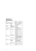
Page 18: ...age transfer at 75 nominal over voltage re transfer at 121 nominal under voltage re transfer at 79 nominal 0 3 ms inverter to line 2 ms line to inverter AVR on line mode on line boost up on line buck...

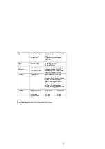
Page 19: ...rgy 320 Joules 2 ms clamping voltage 765 50A Interface D type 9 pin connector provides both RS 232 and contact signal and many functions such as power failure battery low UPS shutdown power failure hi...

Page 20: ...low signals to the PC and receive shutdown signal and scheduled on off time table from the PC Figure 6 D type 9 pin connector 1 contacts normally open 2 signal high minimal 1 second 3 low battery 4 ma...

Reviews: