1
Chapter 1:
Hardware installation
You will require a Phillips screwdriver and, if the cables
connected to your PC are secured with screws, a small flat-
bladed screwdriver.
You will have to open your PC case in order to install the ViCtor
II components. Before continuing, please make a note of the
cable connections before disconnecting them from the PC. You
can now remove the cover from the computer.
Note
Switch off and disconnect your computer from the mains supply before
carrying out any hardware installation work. Failure to do so may cause injury
to users and damage to the equipment.
Find a free PCI slot, remove the cover plate facing the slot,
insert the ViCtor II interface card into the slot, and secure it with
the cover plate screw. PCI slots mostly use white connectors.
ISA type slots, which mostly use black connectors, will not
accept the ViCtor II. If you are in doubt about the correct
installation procedure for expansion cards; consult your PC’s
manual.
Attention
In many computers, the VGA card controlling the VDU also occupies a PCI
slot. This card should not be moved to another PCI slot, as this requires
reinstallation of the Windows 95 drivers, which would result in the loss of your
VDU settings.
You can now replace the cover of the PC case and reconnect
all the cables.
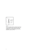
Referring to Figure 1, connect the (optional) camera to the
ViCtor II using the cables supplied. Make sure the yellow plug is
connected to the video output of the camera and the video
input of the ViCtor II. The camera receives its power supply
from an adapter or through a cable connected to the keyboard,
in which case you should select a cable to match your keyboard
connector, which will be either a PS/2 socket or a DIN socket.
Summary of Contents for ViCtor II
Page 1: ...Trust ViCtor II User s Manual version 1 0 vdo adsp ...
Page 10: ...4 ...
Page 12: ...6 ...
Page 16: ...10 ...


