background image

AV15 INSTALLATION MANUAL | TruSteel AutoVap15 Installation Instructions | v. 1.3

27 / 43

1. Place Residue Recovery Tank on the feed side of your process.( NOTE:

Orient your tanks, to keep gauges and vacuum controls accessible to

the operator)

Summary of Contents for AV15

Page 1: ...Copyright 2020 by TruSteel LLC All Rights Reserved AV15 INSTALLATION MANUAL TruSteel AutoVap15 Installation Instructions Version 1 3 ...

Page 2: ...NS 20 AUTOVAP15 ASSEMBLY 20 UNBOXING 22 ASSEMBLY 26 CHILLER FILL STARTUP 32 SYSTEM REQUIREMENTS 32 FILL CHILLER 32 Troubleshooting 33 Alarm Reset Procedure 33 b1AC Set Point 34 ALc1 ALARM ON START UP 35 Contact MTA 35 HEATING SYSTEM FILL STARTUP 36 Prepare Equipment 36 Prepare To Fill PreHeater Use Port 1 37 Fill the System 38 Allow Pressure To Rise In System 39 Power On Heater and Recirculating P...

Page 3: ...the best solution With a recovery rate of up to 20 gallons per hour the AV15 recovers up to 99 solvent on the first pass with the added benefit of automated solvent discharge Lower your footprint costs and time of operation while eliminating any bottlenecks with the AutoVap Find out why all the leaders in the extraction industry are turning to TruSteel How the AutoVap15 Works The AutoVap15 works b...

Page 4: ...compliance TruSteel is not responsible for setting up the customer facility in order to comply with any local codes The AutoVap15 is C1D2 compliant The ancillary however is not and should be placed outside of the solvent recovery room The chiller unit should be placed in a well ventilated area preferably outside of the facility in the open air on a concrete slab or on the roof The chiller should b...

Page 5: ...e gas heater will require proper ventilation The water heater ideally should be within 30 feet of the AutoVap15 for full efficiency The vacuum pump and heater manifold inline pump should all be outside of the C1D2 solvent recovery room CLICK HERE FOR PDF VERSION CHECKLISTS Use the following checklists to keep track of your projects progress Please print each of the following checklists for your re...

Page 6: ...e Expansion Tank Remote Control Water Heater The heater unit will be delivered directly from the manufacturer Please be aware that the heater will take at least 2 weeks to be manufactured Tracking will be provided when available Heater Model Heater Serial Manifold Package The manifold package will be shipped directly from TruSteel It will include VFD Variable Frequency Drives Taco Recirculating Wa...

Page 7: ... Pump Serial Vacuum Pump Vacuum Pump Model Vacuum Pump Serial AutoVap15 The AutoVap15 will be shipped directly from TruSteel via freight shipment It is separated into 2 crates the Vessel Box and the Coffin Box See Box for Packing Slip Click here to download a copy of a blank packing slip ...

Page 8: ... bypass manifold is installed on the chiller The plumbing for the chiller is complete to the ball valves hose barbs which are on a unistrut on the wall behind where the AV15 will be Water Heater Requirements There is power to the water heater The water heater manifold provided by TruSteel is connected to the heater and mounted securely on the wall The manifold is oriented in the correct position p...

Page 9: ...ntrol for the feed pump is wired Required Commodities to have on site Sump Pump A clean new sump pump 1 2 hp or greater with a short piece of hose with hose fittings used to fill the water heater line 35 gallon CLEAN reservoir 2 15 20 foot hoses with standard hose fittings on both ends Distilled Water At least 50 Gallons of DISTILLED WATER NOT TAP WATER on site Propylene Glycol See Chiller Manual ...

Page 10: ...051 480V 3Ø 13A Water Heater Specifications Plumbing Size 1 HX036 6R 208V 3Ø 99 9A Draw HX033 6T 240V 3Ø 86 6A Draw HX036 6T4 480V 3Ø 43 3A Draw HX033 6S 240 1Ø 137 5A Draw HX016 3R 16kW 208V 3Ø 44 4A Draw HX016 3T 16kW 240V 3Ø 38 5A Draw HX016 3T7 16kW 415V 3Ø 22 3A Draw Gas Heater Hubbell NX200 120V 1 Phase 12A Draw Gas Heater Hubbell NX300 120V 1 Phase 12A Draw Variable Frequency Drive Specific...

Page 11: ...bell model HX Tankless electric water heater is a highly reliable and easily maintained heater designed for operation in a commercial or industrial application The Hubbell HX Tankless heater is compact extremely efficient takes up minimal space and reduces operating costs Electric Water Heater Technical Documents Model HX TX Brochure PDF Model HX TX Written Spec PDF Model HX TX O M Manual PDF ...

Page 12: ...ter Heater Technical Documents Hubbell Model NX Brochure PDF Hubbell NX O M PDF Hubbell NX300 Submittal Sheet PDF Model NX300 Spec PDF Water Heater Requirements See Water Heater Requirements Section AV30 REQUIREMENTS CHECKLIST Link To Helpful Video Important Information 1 The water heater should be placed OUTSIDE of the room that the AutoVap will be running in The heater is NOT C1D2 Place the heat...

Page 13: ...ch for your heater since the flow powers up the heater Commodities Needed By Customer Needed to prime the system and for maintenance 1 You will need a sump pump minimum 25 ft head pressure to prime the system Click Here to Purchase a Sump Pump or see example Amazon com 2 Short piece of garden hose with hose fittings to connect sump pump to manifold intake Click Here to Purchase or see example Amaz...

Page 14: ...TION MANUAL TruSteel AutoVap15 Installation Instructions v 1 3 14 43 MODEL ELECTRICAL HORSEPOWER UNIT DIMENSIONS VR3452 HY1 FC1A00 115V 1Ø 2 5A 1 100 to 1 4 See Submittal Data Information CLICK HERE FOR PDF VERSION ...

Page 15: ...TAEevo range of air cooled chillers are a packaged unit designed for industrial applications They are supplied with hermetic scroll or reciprocating compressors and an innovative finned pack evaporation inside the storage tank Technical Documents Complete Installation Instructions PDF TaeEvoTech Data Sheet SEE CHILLER REQUIREMENTS ...

Page 16: ...e ball valves provided The ball valves are mounted on a unistrut 4 The chiller requires a propylene glycol water mixture Please refer to the Installation Instructions to verify how much propolyene glycol your unit will require Ratio is climate dependant Link to Purchase 5 Please note that the chiller IS NOT powered by the 15 The chiller is not controlled by the AutoVap15 6 Don t forget to wire up ...

Page 17: ...d no more frequent and costly oil change or cross contamination MODEL ELECTRICAL R EQUIREMENTS PUMPING RATE UNIT DIMENSI ONS WEIGHT WELCH 2052 110V 60Hz single phase 0 53 HP 390 watts 2 3 cfm 9 15 7 inches 40 3 Lb Vacuum pump is connected to AutoVap with a braided silicone hose provided by TruSteel The customer may choose to run a discharge line from the vacuum pump in the event that solvent gets ...

Page 18: ...ischarged the Auto Discharge Pump will deactivate There is a second higher float switch in the Solvent Vessel that will automatically STOP the feed pump if triggered This ensures you will never overfill your Solvent Vessel in the event the bottom float mechanism ever fails Technical Documents and Instructions Lenze VFD Installation Manual AC Tech Lenze SMVector NEMA 4X Flyer AC Tech Lenze SMVector...

Page 19: ...piece of hose with hose fittings and 35 gallon reservoir tote used to fill the water heater line Link to Purchase Sump Pump Amazon Link to Purchase Sump Pump Home Depot Link to Purchase Hose Amazon Link to Purchase Reservoir An air compressor dedicated to use with the AutoVap used for discharge at 3 5psi Link to Purchase Air Compressor Home Depot At least 50 gallons of DISTILLED WATER NOT tap wate...

Page 20: ...IONS AUTOVAP15 ASSEMBLY LINK TO AV15 UNBOX VIDEO Tools You will need 2 People Ladder 7 8 Wrench 5 8 Wrench Here is a picture of the AutoVap15 with Auto Discharge fully assembled Note this picture does not show the hoses from the chiller and water heater the vacuum pump hose or the conduits run to the motors for the pumps ...

Page 21: ...AV15 INSTALLATION MANUAL TruSteel AutoVap15 Installation Instructions v 1 3 21 43 ...

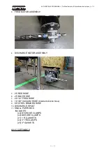
Page 22: ...UAL TruSteel AutoVap15 Installation Instructions v 1 3 22 43 UNBOXING Start by unboxing unwrapping all parts of your AutoVap15 You have 2 crates the AV15 Vessel Box and the AV15 Coffin Box AV15 Vessel Box 1 RESIDUE ASSEMBLY ...

Page 23: ...AV15 INSTALLATION MANUAL TruSteel AutoVap15 Installation Instructions v 1 3 23 43 2 RECOVERYASSEMBLY ...

Page 24: ...R ASSEMBLY 4 DISCHARGE MOTOR ASSEMBLY 5 25 RED HOSE 6 25 BLUE HOSE 7 20 1 2 FEED HOSE 8 10 3 8 VACUUM HOSE braided silicone hose 9 60 STEEL BRAIDED HOSE 10 DISCHARGE SPOUT 11 SMALL PARTS BOX INCLUDES x4 16 HOSE CLAMPS x2 6 HOSE CLAMPS x1 1 5 GASKETS x4 3 TRI CLAMPS x5 3 GASKETS AV15 COFFIN BOX ...

Page 25: ...TALLATION MANUAL TruSteel AutoVap15 Installation Instructions v 1 3 25 43 1 EVAPORATOR ASSEMBLYw COVERS 2 CONDENSER ASSEMBLYw COVERS 3 FEED BLOW OFF ASSEMBLY 4 SPRAYER ASSEMBLY 5 3 90 TC ELBOW 6 PRESSURE GAUGE ...

Page 26: ...AV15 INSTALLATION MANUAL TruSteel AutoVap15 Installation Instructions v 1 3 26 43 ASSEMBLY ...

Page 27: ...ION MANUAL TruSteel AutoVap15 Installation Instructions v 1 3 27 43 1 Place Residue Recovery Tank on the feed side of your process NOTE Orient your tanks to keep gauges and vacuum controls accessible to the operator ...

Page 28: ...l AutoVap15 Installation Instructions v 1 3 28 43 2 Using a ladder connect the Evaporator Tower Assembly to the Residue Recovery Tank using a 3 Triclamp Be sure NOT to pinch or damage the gasket when placing Evaporator Tower Assembly ...

Page 29: ... AutoVap15 Installation Instructions v 1 3 29 43 3 Next connect the Condensing Arm FIRST to the Evaporator Tower Assembly and then to the Solvent Recovery Tank using 3 Triclamps Again take care not to damage the gaskets when connecting ...

Page 30: ...ll Triclamp connections are tight and secure 5 Connect the Feed Pressure gauge assembly to the pre heater via Swagelock connection NOTE Thread Swagelock connection finger tight as much as you can If you cannot complete a few full turns when threading by hand STOP and begin again DO NOT CROSS THREAD ...

Page 31: ...ion 7 Connect Feed Pump to PreHeater Assembly with Braided Stainless Steel Hose 8 Use 1 2 Silicone Feed Hose to feed material to your feed pump clamp hose to feed pump hose barb 9 Cut feed hose line and use the remainder for your discharge pump to discharge solvent into your vessel 10 Connect the 10 of braided silicone hose from the vacuum port to your vacuum ...

Page 32: ...ns Chiller Blue Hose From Connect To Chiller Out from Ball Valve on Wall Condenser Cold In Lower Port on Evaporator flood fills Condenser Cold Out Vessel Cold In Flood Fill Vessel Cold Out Cold Water Return Ball Valve Back to Chiller CHILLER FILL STARTUP SYSTEM REQUIREMENTS Use this chart to determine your recommended propylene water ratio If you have any doubts please call MTA USA The total volum...

Page 33: ...splayed then press set 1 time 11 Now you should see RST reset above ALRN Press set again to reset the alarm and the unit should begin to cycle again 12 Repeat Steps 11 14 until all the air out of the system You will know when the compressor turns on Now the system is Primed and ready to go Troubleshooting If you do not see ALRN after pressing menu toggle between set and menu until ALRN appears on ...

Page 34: ... temperature Low Flow Auto Manual Delayed b1tF Fan thermal alarm Fan jammed ice Manual Instantaneously C n tr Compressor circuit number thermal alarm Running at high temperatures Manual Instantaneously AEht Evaporator inlet high temperature High water temperature Manual Instantaneously b1AC Set Point After the unit is primed you need to lower the freeze point of the reservoir Note Contact MTA to d...

Page 35: ...5 Press the set button once and the upper display red will start flashing Use the down arrow to adjust the parameter to the appropriate value commensurate with the glycol protection temperature 6 Press the set button once more to store the new value 7 Press the set up arrow buttons simultaneously to exit programming mode and return to the main display Monitor chiller operation for several cycles t...

Page 36: ...ficient evaporation as well as having improper flow through the heating system Below are steps to ensure you properly fill the heating system When connecting the hoses make sure to angle the hose barbs located on the AutoVap15 to minimize flow restrictions throughout the system Prepare Equipment WARNING Never try to fill the heating system if the water is hot or if the heater is on 1 Make sure the...

Page 37: ...d place it near the fill ports on the copper manifold 3 Fill the large barrel with 10 12 gallons of distilled water 4 Get a 1 2 hp sump pump attach a garden hose to it and place it in the barrel 5 Connect the hose to the FILL PORT using the coupler supplied 6 CLOSE the ball valve directly in between the FILL PORT and RETURN PORT See 4 in diagram above All other valves throughout the plumbing syste...

Page 38: ...1 Turn on the sump pump to circulate through system and out the RETURN PORT on the Left 2 Watch for air to bubble out of the RETURN PORT hose in the bucket 3 When all air has escaped toggle the HOT WATER BYPASS VALVE located on the bottom of the Residue Recovery Tank See image below 4 Watch for air to bubble out of the RETURN PORT hose on the Left ...

Page 39: ...ll help purge the air out faster Allow Pressure To Rise In System 1 Look at the pressure gauge on the heater manifold and start to close the hose bib on the left 2 Once the pressure reaches above 15 20 PSI make sure both hose bibs fill ports are closed The system is now filled primed 3 Turn off the sump pump Power On Heater and Recirculating Pump and check system for leaks 1 If you haven t already...

Page 40: ...set point 5 The flow rate should be between 10 15 gallons per minute 6 Set the heater temperature to a safe temperature around 95F while we check for leaks 7 Check all your plumbing and the AutoVap system for leaks Check the red hose ports on the AutoVap and anywhere the hot water flows If you do not have any leaks you can proceed to the next step ...

Page 41: ...XTREMELYHOT 2 Get a bucket to capture water from the temperature pressure valve or let the water drain out if plumbed properly 3 Lift up on the Temperature pressure valve on the heater manifold and set accordingly Electric heater set pressure between 15 20 Gas heater set the pressure to 45 55 PSI 4 The heating system is now filled primed and ready to operate Contact Hubbell Support For questions c...

Page 42: ...AV15 INSTALLATION MANUAL TruSteel AutoVap15 Installation Instructions v 1 3 42 43 ...

Page 43: ...ment to be delivered from date of purchase Booking 4 weeks out from the date of purchase may not be realistic Installation Date The TruSteel Installation Team normally consists of 2 people They will do their best to arrive within the expected hours discussed An install typically takes 1 2 days During the installation the TruSteel personnel will give you an idea of when the system will be ready for...

Reviews: