background image

10 

Installation Guide


Installation 

This section provides information on how to 

install the cameras.


Installation environment 

When installing your product, consider these 

factors:


Electrical

Install electrical wiring carefully. 

It should be done by qualified service 

personnel. Always use a proper 12 VDC 

UL listed Class 2 CE certified power supply 

or a proper 24 VAC power supply, 

depending on the camera. Do not overload 

the power cord or adapter


Ventilation

: Ensure that the location 

planned for the installation of the camera is 

well ventilated.


Temperature: 

Do not operate the camera 

beyond the specified temperature, humidity 

or power source ratings. The operating 

Summary of Contents for TVD-6101

Page 1: ...P N 1073684 EN REV C ISS 09JUN21 TruVision HD TVI Dome Camera Installation Guide...

Page 2: ......

Page 3: ...ion 7 Installation 10 Installation environment 10 Mounting the HD TVI fixed lens dome camera TVD 6102 12 Mounting the HD TVI VF motorized lens dome camera TVD 6101 TVD 6103 TVD 6104 TVD 6105 15 Specif...

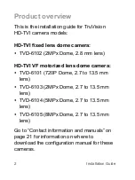
Page 4: ...2MPx Dome 2 8 mm lens HD TVI VF motorized lens dome camera TVD 6101 720P Dome 2 7 to 13 5 mm lens TVD 6103 2MPx Dome 2 7 to 13 5 mm lens TVD 6104 5MPx Dome 2 7 to 13 5 mm lens TVD 6105 8MPx Dome 2 7 t...

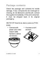
Page 5: ...onents are damaged or missing do not attempt to use the unit contact the supplier immediately If the unit is returned it must be shipped back in its original packaging HD TVI VF fixed lens dome camera...

Page 6: ...4 Installation Guide Template Installation guide Torx wrench 12 VDC connector Two terminal connector with positive and negative indicators Equipment disposal sheet...

Page 7: ...n Guide 5 HD TVI VF motorized lens dome camera TVD 6101 TVD 6103 TVD 6104 TVD 6105 Camera with power and video output cable harness 4 screws and 4 anchors 3 screws to connect the camera to the back bo...

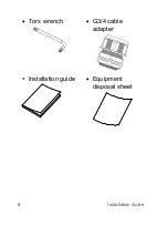
Page 8: ...6 Installation Guide Torx wrench G3 4 cable adapter Installation guide Equipment disposal sheet...

Page 9: ...Installation Guide 7 Camera description Figure 1 HD TVI fixed lens dome camera TVD 6102 1 Base 2 Lens assembly 3 Bubble assembly 4 TVI output 5 12 VDC power 6 TVI 960H analog switch button...

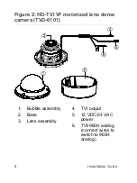
Page 10: ...stallation Guide Figure 2 HD TVI VF motorized lens dome camera TVD 6101 1 Bubble assembly 2 Base 3 Lens assembly 4 TVI output 5 12 VDC 24 VAC power 6 TVI 960H analog connect wires to switch to 960H an...

Page 11: ...Installation Guide 9 HD TVI VF motorized lens dome camera TVD 6103 TVD 6104 TVD 6105 1 Bubble assembly 2 Base 3 Lens assembly 4 TVI output 5 12 VDC 24 VAC power 6 TVI 960H analog switch button...

Page 12: ...uld be done by qualified service personnel Always use a proper 12 VDC UL listed Class 2 CE certified power supply or a proper 24 VAC power supply depending on the camera Do not overload the power cord...

Page 13: ...era and also create the danger of electric shock Servicing Do not attempt to service this camera yourself Any attempt to dismantle this product will invalidate the warranty and may also result in seri...

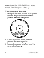
Page 14: ...plate place it level against the mounting surface and mark the position of the mounting holes 2 Following all local codes drill and prepare the mounting holes 3 Loosen the screws with Torx wrech to re...

Page 15: ...Installation Guide 13 4 Securely fasten the mounting base to the mounting surface with the screws...

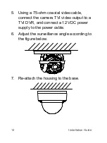
Page 16: ...a 75 ohm coaxial video cable connect the camera TVI video output to a TVI DVR and connect a 12 VDC power supply to the power cable 6 Adjust the surveillance angle according to the figure below 7 Re a...

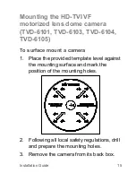
Page 17: ...1 TVD 6103 TVD 6104 TVD 6105 To surface mount a camera 1 Place the provided template level against the mounting surface and mark the position of the mounting holes 2 Following all local safety regulat...

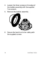
Page 18: ...Installation Guide 4 Loosen the three screws on the edge of the bubble assembly with the supplied Torx wrench 5 Remove the bubble assembly 6 Secure the back box to the ceiling with the supplied screw...

Page 19: ...cable routing outside of the camera when required 7 Using a 75 ohm coaxial video cable connect the camera TVI video output to a TVI DVR and connect a 12 VDC or 24 VAC 8 Align the camera with the back...

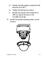
Page 20: ...18 Installation Guide 9 Adjust the surveillance angle a View the camera image on a monitor b Rotate the panning table to adjust the pan direction 0 to 355 c Loosen the tilting lock screw...

Page 21: ...ate the tilting table to adjust the tilt direction 0 to 90 e Tighten the tilting lock screw f Rotate the camera lens holder 0 to 355 to adjust the lens to the surveillance angle 10 Install the bubble...

Page 22: ...mA 24 VAC Max 324 mA Max 7 W TVD 6102 12VDC Max 282 mA Max 3 4 W TVD 6103 12 VDC Max 625 mA 24 VAC Max 480 mA Max 7 5 W TVD 6104 12 VDC Max 667 mA 24 VAC Max 340 mA Max 8 W TVD 6105 12 VDC Max 685 mA...

Page 23: ...n TVD 6102 82 4 111 mm 3 2 4 4 in Contact information and manuals For contact information and to download the latest manuals go to the web site of your region EMEA https firesecurityproducts com Manua...

Page 24: ...nd international copyright law Trademarks and patents TruVision names and logos are a product brand of Aritech a part of Carrier Other trade names used in this document may be trademarks or registered...

Page 25: ...at his own expense FCC conditions This device complies with Part 15 of the FCC Rules Operation is subject to the following two conditions 1 This device may not cause harmful interference 2 This Devic...

Page 26: ...cyclethis info Product warnings and disclaimers THESE PRODUCTS ARE INTENDED FOR SALE TO AND INSTALLATION BY QUALIFIED PROFESSIONALS CARRIER FIRE SECURITY CANNOT PROVIDE ANY ASSURANCE THAT ANY PERSON O...

Page 27: ...firesecurityproducts com Australian New Zealand https firesecurityproducts com au Product documentation Please consult the following web link to retrieve the electronic version of the product document...

Page 28: ......

Reviews: