background image


Page 15 

SERVICE & MAINTENANCE  - PETROL & DIESEL  

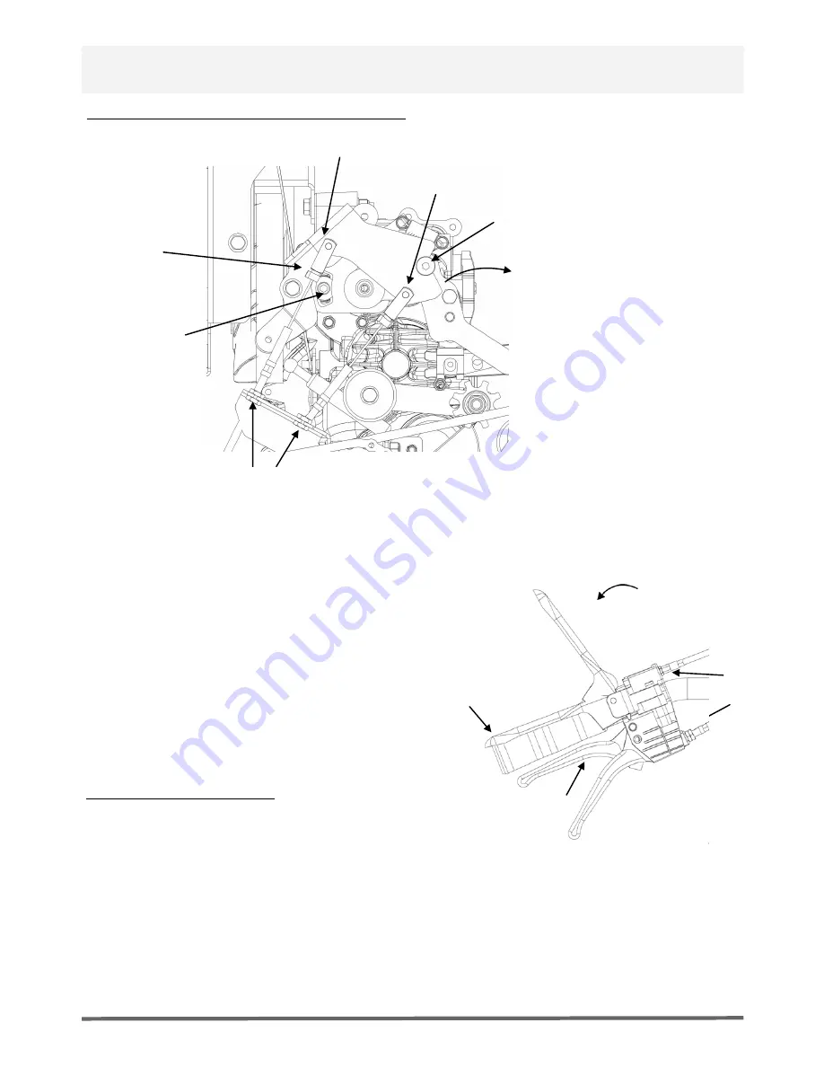
PUMP CONTROL SETTINGS & ADJUSTMENT 

FORWARD CONTROL CABLE


REARWARD CONTROL CABLE


DIRECTION SAFETY PIN 

(SHOWN IN LOCKED POSITION)


CABLE ADJUSTMENT NUTS


PUMP NEU-

TRAL SETTING 

SCREW


DEPRESS DEADMAN LEVER 

TO DISENGAGE PIN


PUMP DIREC-

TION BRACKET


1: Adjust Deadman lever cable tension if required, see engage angle. Adjust cable adjustment nuts. With Deadman 
lever in fully pressed position ensure the direction safety pin is clear of control plate (see above) 

2: Adjust forward/reverse direction levers cable tension if 
required, ensure 3mm - 5mm gap when fully pressed. 
Adjust cable adjustment nuts. 
 
3: Ensure that with forward lever fully pressed the pump 
direction bracket turns  
       15 degree forward direction 75 rpm @ wheels 
 
4: Ensure that with rearward lever fully pressed the pump 
direction bracket turns  
       5 degree rearward direction 30 rpm @ wheels 


PUMP NEUTRAL SETTING 

1: Adjust pump neutral setting if required if machine creeps 
forwards/backwards when in neutral,  

 

disconnect forward and rearward control cables 

 

fully press Deadman lever to disengage the direction safety 
pin 

 

loosen pump neutral setting screw 

 

adjust angle of pump control bracket by rotating forward/
backward until no creep


 

re tighten pump neutral setting screw when wheel rotation is 
0 rpm


CABLE 

ADJUSTMENT 

NUTS


DEADMAN LEVER 

ENGAGE ANGLE


10-

20 degree


DEADMAN LEVER 

FULLY PRESSED 

POSITION


DIRECTION LEVERS 

GAP TO HANDLE 5MM  

WHEN FULLY  

PRESSED


Summary of Contents for BENDI 300D

Page 1: ...OPERATOR MANUAL PARTS LIST MACHINE MODELS BENDI 300G BENDI 300D BENDI 300E BENDI 450G BENDI 450D BENDI 450E SERIAL Numbers After B151040...

Page 2: ...4 Service Pump Control Settings Adjustment 15 Operating Instructions Electric 16 Operating Instructions Battery Charger 16 Warning Symbols Decals 17 Service Maintenance Electric Problem Solving 18 21...

Page 3: ...amended by 89 336 EEC 92 31 EEC 93 68 EEC The Waste Electrical and Electronic Equipment WEEE 2002 96 CE the low voltage directive 2006 95 CE BS EN ISO 12100 1 2003 Safety of machinery and associated h...

Page 4: ...Model TRUXTA Type Serial No B300D B450D R300D The technical documentation is held by TUFFTRUK Ltd Address above The conformity assessment procedure followed was in according with annex VI of the Direc...

Page 5: ...me Model TRUXTA Type Serial No B300G R300G The technical documentation is held by TUFFTRUK Ltd Address above The conformity assessment procedure followed was in according with annex VI of the Directiv...

Page 6: ...Name Model TRUXTA Type Serial No B450G The technical documentation is held by TUFFTRUK Ltd Address above The conformity assessment procedure followed was in according with annex VI of the Directive N...

Page 7: ...odel TRUXTA Type Serial No B300E B450E ELECTRIC OPTIONS The technical documentation is held by TUFFTRUK Ltd Address above The conformity assessment procedure followed was in according with annex VI of...

Page 8: ......

Page 9: ...m 450kg 10 6ft 0 3m 300kg 7ft 0 2m 450kg 10 6ft 0 3m Unladen Weight kg 170 180 201 219 224 255 Working Gradient 25 25 25 Drive Controls Hydrostatic System 24v Motor Gearbox Brake System Fail safe dead...

Page 10: ...he site or servicing it During use the engine becomes very hot allow the engine to cool before touching it Never leave the engine running and unattended Never remove or tamper with any guards fitted t...

Page 11: ...le fuel vapours and avoid contact with your skin Wash fuel splashes immediately If you get fuel in your eyes Irrigate with copious amounts of water and seek medical attention as soon as possible Exhau...

Page 12: ...nto place PRE START UP INSPECTION The following pre start up inspection must be performed before the start of each work session or after every four hours of use whichever is first Please refer to the...

Page 13: ...e ignition key on Move throttle to desired speed Grip the dead man lever and hold it down Use the forward and reverse levers to control direction of travel and speed Never press both levers at once or...

Page 14: ...nt to dry then soak in clean engine oil and squeeze out the excess oil If the engine smokes during start up then too much oil has been left on the foam Paper Element Tap the element on a hard surface...

Page 15: ...nt nuts 3 Ensure that with forward lever fully pressed the pump direction bracket turns 15 degree forward direction 75 rpm wheels 4 Ensure that with rearward lever fully pressed the pump direction bra...

Page 16: ...e electric motor housing Clean only with a cloth or compressed air TRANSMISSION DRIVE CHAINS Clean and lubricate the 3 transmission drive chains once a year OPERATING INSTRUCTIONS CHARGING ELECTRIC TR...

Page 17: ...ELECTRIC TRUXTA WARNING SYMBOLS DECALS Page 17...

Page 18: ...Page 18 ELECTRIC TRUXTA WIRING DIAGRAM DIAGNOSTICS TROUBLESHOOTING...

Page 19: ...format Err the codes are listed in Table 4 The troubleshooting chart Table 5 describes the faults and their possible causes the faults are listed in alphabetical order Whenever a fault is encountered...

Page 20: ...DIAGNOSTICS TROUBLESHOOTING TRUXTA ELECTRIC Page 20...

Page 21: ...ELECTRIC TRUXTA DIAGNOSTICS TROUBLESHOOTING Page 21...

Page 22: ...0 A CABLE SKIP RELEASE B 1 16 75 01900 0 CABLE ASSY FWD ELECTRIC 1 ELECTRIC OPTION 17 75 02000 0 CABLE ASSY DEADMAN ELECTRIC 1 ELECTRIC OPTION 18 75 02100 0 CABLE ASSY REV ELECTRIC 1 ELECTRIC OPTION 1...

Page 23: ...TOP FRAME STEERING ASSEMBLY Page 23 800 18003 0 25 04 16...

Page 24: ...25MM 1 58 8 10006 0 NUT M10 NYLOC 4 DIESEL OPTION 20 101 01200 E SKIP CATCH BRACKET WA 1 59 8 10003 1 NUT M10 BZP 2 21 101 02100 4 FRAME SKIP CARRIER W A 1 60 4 1204 1 WASHER M12 FORM A BZP 2 22 101...

Page 25: ...Page 25 FRONT CHASSIS ASSEMBLY 800 18002 0 19 04 16...

Page 26: ...4 1007 A WASHER FLAT M10 FORM A BZP 4 25 8 19001 0 UNF 3 4 NUT 1 81 8 10006 0 NUT M10 NYLOC 6 26 6 0001 0 ADAPTOR ST 7 16 UNC 1 4 BSP SS 1 82 7 10004 1 SCREW SET M10 X 20 BZP 2 27 6 0002 0 ELBOW 90DEG...

Page 27: ...Page 27 REAR ASSEMBLY ALL ENGINE MODELS 800 18000 0 19 04 16...

Page 28: ...53 70 01200 0 MOTOR 1300W 1 54 6 2200 0 GEARBOX 1300W 1 55 21 1800 0 KEY 8x7X40 LG ROUND END 1 56 7 8010 0 SCREW CAP M8X25MM SCKT HD BZP 4 57 21 1700 0 KEY 5x5x20 LG ROUND END 1 58 6 2100 0 GEARBOX T...

Page 29: ...Page 29 ELECTRIC REAR ASSEMBLY 800 18001 0 19 04 16...

Page 30: ...PART NUMBER DESCRIPTION QTY NOTES 1 73 0100 H FLAT BED W A 1 2 73 0111 C FLAT BED BASE 1 3 73 0112 B FLAT BED REAR 1 4 73 0900 G FLATBED REAR WA 1 5 8 10006 0 NUT M10 NYLOC 20 6 4 1005 1 WASHER FLAT...

Page 31: ...e spark plug TRUXTA and or their recognised agents directors employees or insurers will not be held liable for consequential or other damages losses or expenses in connection with or by reason of or t...

Page 32: ...MPTON STREET TETBURY GLOUCESTERSHIRE GL8 8LD Tel 01666 500123 truxtasales tufftruk co uk Op Manual 06 06 2016 Your local TRUXTA Dealer EUROPE ROW TRUXTA TUFFTRUK LTD THE CROFT SHEEN BUXTON DERBYSHIRE...

Reviews: