background image

© Trynex International 2009      L1188

GR4 — 5

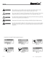
Before attempting any procedure in this book, these safety instructions must be read and understood by all workers who 
have any part in the preparation or use of this equipment.

For your safety

,warning and information decals have been placed on this product to remind the operator of safety precautions.  

If anything happens to mark or destroy the decals, please request new ones from Snowex. 

Remember,

 most accidents are preventable and caused by human error. 

Exercising of care and 

precautions must be observed to prevent the possibility of injury to operator or others!

Never

 operate equipment when under the 

influence of alcohol, drugs, or medication that might

alter your judgment and/or reaction time.

.r

i

a

h


d

e

n

i

a

r

t

s

e

r

n

u


d

n

a


g

n

i

h

t

o

l

c


g

n

i

t

t

i

f


e

s

o

o

l

 l

l

a


e

r

u

c

e

s

 ,

r

e

d

a

e

r

p

s


e

h

t


h

t

i

w


g

n

i

k

r

o

w


e

r

o

f

e

B


d

l

u

o

c


s

i

h

t


o

d


o

t


e

r

u

li

a

F


 .

l

a

t

e

m


t

s

n

i

a

g

a

 l

a

t

e

m


g

n

i

k

r

o

w


n

e

h

w


s

d

l

e

i

h

s


e

d

i

s


h

t

i

w


s

e

s

s

a

l

g


y

t

e

f

a

s


r

a

e

w


s

y

a

w

l

A

 
result in serious injury to the eyes.

Never

 allow children to operate or climb on equipment.

Never

 weld or grind on equipment without having a fire extinguisher available.

Always check areas

 to be spread to be sure no hazardous conditions or substances are in the area.

Always inspect unit for defects:

 broken, worn or bent parts, weakened areas on spreader or mount.


Always shut off

 vehicle and power source before attempting to attach or detach or service spreader 

unit.  Be sure vehicle/power source is properly braked or chocked.


Always make sure personnel are clear of areas of danger when using equipment. 

Always keep hands, feet, and clothing away from power-driven parts.

Remember,

 it is the owner’s responsibility to communicate information on safe usage and proper 

maintenance of all equipment.

Safety 

Summary of Contents for SnowEx SP-125

Page 1: ...GR4 1 Trynex International 2009 REV 004 L1188 SP 125 US 100 SP 225 US 200 Madison Heights Michigan 48071 800 725 8377 www snowexproducts com...

Page 2: ...4 SAFETY 5 6 PREPARATION OPERATIONS SERVICE SPREADER PARTS DIAGRAMS 7 12 SP 125 US 100 ACCURATE FLOW SP 125 US 100 ACCURATE FLOW COMPLETE DRIVE ASSEMBLY SP 225 US 200 MULTI PURPOSE SP 225 US 200 MULT...

Page 3: ...your Snowex Dealer THIS SIGN SHOULD ALERT YOU The Society of Automotive Engineers has adopted this SAFETY ALERT SYMBOL to pinpoint characteristics that if NOT carefully followed can create a safety h...

Page 4: ...bene ts you are about to recognize are that of time money and e ort We welcome you to the world of Snowex Performance Registration Record the following information in this manual for quick reference...

Page 5: ...c e s r e d a e r p s e h t h t i w g n i k r o w e r o f e B d l u o c s i h t o d o t e r u l i a F l a t e m t s n i a g a l a t e m g n i k r o w n e h w s d l e i h s e d i s h t i w s e s s a l...

Page 6: ...water softener salt Never leave material in hopper for long periods of time Be aware that all ice melters are hygroscopic and will attract atmospheric moisture and harden up Always inspect pins and l...

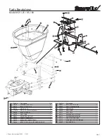
Page 7: ...2 KNOB 5 16 18 X 3 4 D6304 CABLE T HANDLE 10 D6305 BULKHEAD CABLE FITTING D6308 BOLT 5 16 18 X 3 4 HEX HEAD W HOLE Description Qty 4 2 14 1 2 1 1 1 1 1 D6462 BOLT 5 16 18 X 1 3 4 D6703 GATE STOP INDIC...

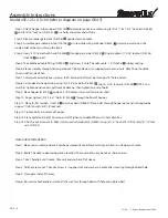
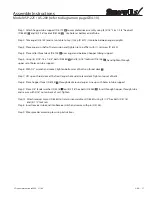
Page 8: ...5 16 locknuts D 6138 NOTE You must rst tighten bottom bolts pull front of deck up then tighten top set of bolts Step 9 Place hopper D 6753 on deck 5 8 hole must be used for spinner shaft Step 10 Fing...

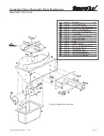
Page 9: ...ent Clevis 1 D 6172 10 32 x 5 8 Serr Flange Bolt 2 D 6140 5 16 18 x 3 8 S S Set Screw 1 D 6750 10 Plastic Spinner 1 D 6232 Motor Drive Coupler 1 r 1 o t a t i g A 5 0 4 6 D D 6410 Motor 12 Volt DC 1 D...

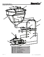
Page 10: ...Q n o i t p i r c s e D o N t r a P y e K D 4318 3 8 Fender Washer 4 t 12 u n k c o L 6 1 5 8 3 1 6 D D 6462 5 16 18 x 1 3 4 HHCS 12 1 54 2 7 cu ft Salter Hopper Yellow 7 6 D 1 k c e D t a o r h T r e...

Page 11: ...x 1 3 4 bolts D 6462 and 4 5 16 locknuts D 6138 hand tighten through upper set of holes on tube support Step 6 With 1 2 wrench and socket tighten bottom set of bolts on throat deck Step 7 Lift up on t...

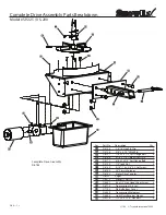
Page 12: ...ent Clevis Pin 1 D 6172 10 32 x 5 8 Serr Flange Bolt 2 D 6140 5 16 18 x 3 8 S S Set Screw 1 D 6750 10 Plastic Spinner 1 D 6232 Motor Drive Coupler 1 r 1 e g u A 2 2 1 6 D D 6410 Motor 12 Volt DC 1 D 6...

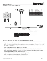
Page 13: ...double female black wire jumper attach the black wire from the power harness to the black wire of the vehicle harness Step 6 Install rubber weatherproof boot on switch before nishing installation Ste...

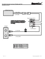
Page 14: ...D 6474 Mini Control 1 D 6486 325 Harness 1 D 6748 25 Amp Breaker 1 25 AMP Pos Red Neg Black Neg Black Pos Red 12 VOLT BATTERY On O Switch Speed Control Knob SPREADER MOTOR IMPORTANT In the o season re...

Page 15: ...ght Not To Exceed 240 lbs Gross y t Q n o i t p i r c s e D o N t r a P y e K D 4315 Lock Knob Assembly FLM 175 Only 2 D 6426 Fork Lift Mount Frame FLM 1 D 4116 1 2 13 x 1 1 2 Hex Bolt 8 8 r e h s a W...

Page 16: ...eceiver tube mount 1 2 e r i t r e l i a r T 1 4 4 6 D D 6442 5 8 13 x 7 Hex bolt special 2 D 6443 5 8 Flat washers 4 MAXIMUM LOAD WEIGHT NOT TO EXCEED 240 LBS GROSS TRAILER MOUNT ASSEMBLY INSTRUCTION...

Page 17: ...ts Breakdown Model TPM 175 CAUTION MAXIMUM OF 240 LBS GROSS WEIGHT CAN BE PUT ONTO MOUNT Key Part No Description Qty D 4133 5 16 Linch Pin 2 D 4135 2 5 16 Hairpin Clip 1 D 4136 5 8 x 5 1 2 Hitch Pin 1...

Page 18: ...o position and insert into vehicle receiver mount Install hitch pin with clip Step 5 Remove swing arm hitch pin and swing spreader out on drivers side at this time use a spray lubricant such as automo...

Page 19: ...air Pin Clip 2 D 4136 5 8 x 5 1 2 Hitch Pin 2 D 6246 1 2 13 x 2 1 2 Hex Bolt 2 D 4318 3 8 Fender Washer 8 y t Q n o i t p i r c s e D o N t r a P y e K D 6420 3 8 16 x 2 Truss Bolt Full Thread 8 D 642...

Page 20: ...lower weld nut on the spreader bracket assembly Adjust rubber CLUB CAR CARRYALL Step 1 Remove the bed tailgate and bottom angle trim Also remove the two rear carriage bolts from the oor of the bed Ste...

Page 21: ...hopper for long periods of time as salt is hygroscopic and will attract atmospheric moisture and harden up SPREADING TIPS Never exceed 10 m p h when spreading For a wider pass increase spinner speed...

Page 22: ...Trynex International 2009 L1188 GR4 22 THIS PAGE INTENTIONALLY LEFT BLANK...

Page 23: ...use only original manufacturer s parts Failure to do so will void warranty Use dielectric grease on all electrical connections to prevent corrosion at the beginning and end of the season and each tim...

Page 24: ...g instructions and safety messages before servicing your spreader Preliminary Checks Be sure all electrical connections are tight and clean Be sure nothing is jammed in the hopper Motor doesn t run Co...

Page 25: ...SMISSION CHECK WITH TEST KIT TEST TURN SHAFT BY HAND SHOULD TURN FREELY CORROSION AT CONNECTION CLEAN OR REPLACE DON T FORGET USE DIELECTRIC GREASE DON T FORGET USE DIELECTRIC GREASE BAD ELECTRICAL CO...

Page 26: ...t be made to the dealer from where the product was purchased unless otherwise authorized by Snowex Snowex reserves the right to determine if any part is defective and to repair or replace such parts a...

Page 27: ...your Trynex Dealer sold you the correct product for your needs application Yes No 10 How would you rate your overall satisfaction with your SnowEx Dealer 11 How would you rate your overall satisfacti...

Reviews: