background image

6

DESIGN AND APPLICATION:

Fig.B 12. 

Pin

The  rotary  buffer  (hereinafter  referred  to  as “buffer”)  is  a  hand-held 
power  tool  driven  by  a  single-phase,  commutator-type  motor.  It  is 

Fig.C  14. 

Fixing screws with hex socket

equipped with an auxiliary handle that can be set in two positions.

15. 

Allen (hex) key 

Class II equipment (double insulation).

Fig.E 16. 

Spindle

17. 

Clamping nut

The buffer is designed for polishing metal surfaces, plastic products and 
painted surfaces, including vehicles. 

18.


Locking wrench

This electric tool is designed for jobs with medium intensity. It is not 

TECHNICAL DATA:

suitable for long-term operation under heavy duty conditions. 

Do never 

use  the  tool  for  applications  that  need  use  of  professional 
equipment. 

BEFORE YOU START:

1. Make sure that electric parameters of the power voltage correspond 

to parameters of the electric tool according to specifications on the 
rating plate. 

2. Make sure that the On/Off switch (

8

) of the electric tool is in its Off 

THE SET CONTAINS:

position. 

ź

Buffer - 1piece

3. While working with a power cord extension make sure that electric 

ź

Auxiliary handle -1piece

parameters of the extension cable and cross-sections of its wires are 

ź

Fixing screws with hexagonal socket - 2 pieces

appropriated for corresponding parameters of the electric tool. The 

ź

Buffing disk - 1piece

extension cable must be fully uncoiled. 

ź

Clamping nut -1piece

n


Installing the auxiliary handle

ź

Locking wrench -1piece

ź

Allen (hex) key -1piece

ź

Buffing pad -1piece
Transport

ation


case

 -1 piece

NOTE: 

For safety reasons always use its auxiliary handle during operation. 

Warranty card -1 piece

Set the auxiliary handle (

4

) to align its pin (

12

) with groove (

13

) in the 

-1 piece

power tool head body (fig. 

B

).

Set fixing screws with hex socket (

14

) and turn them using the Allen key 

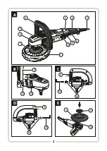
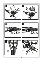
DRAWING DESCRIPTION


(see pages 2-3)

:

(

15

). The auxiliary handle (

4

) can be installed in two ways as shown in 

Fig.A

1. 

Buffing disk 

Fig. 

C

 and 

D

, thus selecting the most comfortable setting. 

 2. 

Arrow that indicates rotation direction

n


Installing and removing the buffing disk

 3. 

Spindle lock button 

ź

Put the buffer with spindle (

16

) upwards. Place the buffing disk (

1

 4. 

Auxiliary handle 

with its bottom protruding part onto the spindle pin to engage the 

 5. 

Speed adjustment knob

disk on the spindle.

 6. 

Main handle

ź

Screw the clamping nut (

17

) onto the spindle to fix the disk securely 

 7. 

Power cord 

(fig. 

E

).

8. 

Switch

ź

Press the spindle lock button (

3

)


and tighten the locking nut exerting 

9. 

Locking lever

slight  pressure  using  the  locking  wrench  (

18

)  provided,  as  during 

10.


Brush-holder

operation the nut tightens up automatically. Following the above-

11.


Buffing pad

mentioned tip will result in avoiding damage to the reducer casing 

Each application of the tool not in line with the intended use as specified 
below is strictly forbidden and makes the warranty terms null and void. 
The  manufacturer  shall  not  be  held  responsible  for  possible 
consequential damage that may arise due to or in connection with such 
application. 
Any modifications of the tool by the user relieve the manufacturer from 
responsibility  for  any  damage  and  injuries  to  the  user  and  the 
surroundings.
Proper use cannot guarantee that no residual risk will occur. Due to the 
design of the machine, the following risks may occur:


-

catching and entangling clothes by moving parts;

hearing  impairment  in  case  of  long-term  operation  without  ear


protectors; 

-   

eye injury resulted from throwing off buffed material particles;

-  t

hrowing a machined part or pieces of a machined part

;


-  emission dust hazardous for human health when works are carried out 

in closed rooms (confined areas).

WARNING!  Prior  to  installation  and  adjustment 
always disconnect the plug from the mains socket. 

ź

ź

ź

O

perating instruction 

13.


Groove

Rated voltage


230-240 

V


Rated frequency 


50 

Hz


Power consumption


                        130

W


Max

. s

peed


under no-load conditions

rpm


33

00 

Max. disk diameter


180


mm


Spindle thread  


M14

Equipment class  


II

Power cord length


5


m

Weight


3,6

 к

g

Sound pressure level (LpA)

 K=3


dB(A)


               dB(A)


93


Sound power level (LwA)


K=3


dB(A)                          

dB(A)


104


Vibration level according to EN 60745-1:2009  

2

(measuring tolerance 

K=

1

,

5m/s

)

polishing the surface 

a  

h AG

6

,

972


2

m/s

Summary of Contents for TMA1300K

Page 1: ...ugi Operating instruction Instruc iuni de folosire RO Lieto anas instrukcija LV RU POLERKA OBROTOWA ROTARY BUFFER MA IN DE LUSTRUIT ROTATIV ROT CIJAS PUL ANAS MA NA 9 4 14 20 25 TMA1300K 1300W HU Has...

Page 2: ...2 A 1300W 1 2 3 4 5 7 8 9 10 11 B 12 13 C D 14 14 15 4 15 4 E 17 1 16 13 00 W 6 4...

Page 3: ...STOP 1 2 2 8 1300W 9 START 1 2 8 1300W 3 F 18 3 H G I 17 11 1 13 00 W 13 00 W 1300W K J 10 5 6 mm...

Page 4: ...al heating radiators and refrigerators Touching earthed or grounded surfaces increases the risk of electric shock c Donotexposeyourpowertooltorainordampenvironments Waterpenetratingthetoolincreasesthe...

Page 5: ...power tool in its original packaging to provide clearance Immobilizing the object in a vice or a clamping device is protectionagainstmechanicaldamage saferthanholdingitinyourhand WARNING General warn...

Page 6: ...tion direction n Installingandremovingthebuffingdisk 3 Spindle lock button Put the buffer with spindle 16 upwards Place the buffing disk 1 4 Auxiliary handle with its bottom protruding part onto the s...

Page 7: ...perate with serious disturbances When poor Depending on the material being buffed the power tool speed can be condition of brushes is found out they must be replaced with new ones adjustedwithintheran...

Page 8: ...et PROTECTIONOFTHEENVIRONMENT 03 228Warsaw POLAND NOTE The symbol nearby denotes that old equipment must ThisapplianceisinconformitywithnationalandEuropeanstandardsas never be thrown away together wit...

Page 9: ...rat kontrolinadelektronarz dziem a Wtyczki elektronarz dzi musz pasowa do gniazdek Nigdy w aden spos b nie nale y przerabia wtyczki Nie nale y u ywa adnych przed u aczy w przypadku elektronarz dzi maj...

Page 10: ...cznewr kachnieprzeszkolonychu ytkownik w elektronarz dzia niegwarantujebezpiecznegou yciaiobs ugi e Elektronarz dzia nale y konserwowa Nale y sprawdza c rednice otworu talerzy polerskich i ko nierzy m...

Page 11: ...o e wej w Talerzpolerski 1szt kontaktzpowierzchni nakt r jestod o one przezcomo nastraci Nakr tka zaciskowa 1szt kontrol nadelektronarz dziem wide kowy m Nale y regularnie czy ci szczeliny wentylacyjn...

Page 12: ...ia Zaleca si stosowanie jak 1 nacisn d wigni blokuj c 9 wkierunkustrza ki patrz rys H najkr tszych przed u aczy Przed u acz powinien by ca kowicie rozwini ty 2 nacisn w cznik 8 Abyzatrzyma urz dzeniew...

Page 13: ...ci chroni przed TRANSPORT wilgoci i zapyleniem Warunki przechowywania powinny wyklucza mo liwo uszkodze mechanicznych oraz wp yw szkodliwych Urz dzenie transportowa i sk adowa w kufrze transportowym...

Page 14: ...RCD TMA1300K 14...

Page 15: ...15 a a...

Page 16: ...16...

Page 17: ...1 1 1 1 1 1 1 2 3 A 1 2 3 4 5 6 7 8 9 10 11 B 12 C 14 15 E 16 17 18 1 2 8 1 3 1 2 1 13 17 240 230 50 1300 3300 180 M14 II 5 3 6 LpA K 3 A A 93 LwA K 3 A A 104 EN 60745 1 2009 2 1 5 ah AG 6 972 2...

Page 18: ...18 n n 8 8 9 1 9 4 H 12 13 2 8 B 14 15 4 8 D n 16 1 1 2 I 17 3 18 n J 600 3300 8 5 1 6 F 6 1 n n G 1 11 n 3...

Page 19: ...19 n 10 5 7 n K 6 34 03 228 PROFIX...

Page 20: ...departe desursedec ldur ulei muchiiascu itesaup r i nmi care Cabluriledeterioratesau ncurcatecrescrisculdeelectrocutare e n cazul n care unealta electric este folosit n aer liber conectarea trebuie ef...

Page 21: ...sc zute saudup operioad ndelungat de f Folosi imijloaceledeprotec iepersonal nfunc iedetipul nefolosire este recomandat pornirea uneltei electrice f r delucru purta imasc deprotec iecareacoper toat fa...

Page 22: ...ixare Ma ina de polisat este destinat lustruirii suprafe elor metalice 18 Cheie furc elementelor din materiale plastice precum i a suprafe elor l cuite inclusivavehiculelormecanice SPECIFICA II Toate...

Page 23: ...iile produc torului Nu folosi i mijloace de ungere de gel ATEN IE Nuap sa ibutonuldeblocareaaxului 3 ntimpulfunc ion rii pentrulustruire uneltei Acestlucrupoateduceladeteriorareaunelteielectrice Past...

Page 24: ...aparaturiiuzate At t nPolonia c t i nEuropase descoperirea periilor uzate trebuiesc nlocuite cu perii noi Indiferent organizeaz sau deja exist sistemul de culegere a aparaturii uzate n periiledec rbu...

Page 25: ...iezem t m vai ar masu savienot m da m pieaug elektrisk sstr vastriecienarisks c Nedr kst pak aut elektroinstrumentus uz lietus vai mitruma iedarb bu Gad jum ja elektroinstrument iek st dens pieaug ele...

Page 26: ...ecie ams p rbaud t vai tie nav boj ti vai lietot g Elektroinstrumentu apr kojumu darba instrumentus un citu neboj tu instrumentu P c darba instrumenta tml nepiecie ams lietot saska ar o instrukciju em...

Page 27: ...s kuriem nepiecie ams 6 Galvenais rokturis dzes jo ais idrums dens vai citu dzes anas idrumu 7 Baro anas vads lieto anavarnovestl dzelektrisk sstr vastriecienam 8 Sl dzis 9 Blo anas svira 10 Ogl u tur...

Page 28: ...rpstu t lai disks b tu rezult t navdro iunstabilinovietots prec zinostiprin ts z m E Nepiecie ams izvair ties no p rm r ga spiediena uz pul anas disku Nospiest v rpstas blo anu 3 un ar pievienoto dak...

Page 29: ...RA OT JS ier ce ir saska ar valsts un Eiropas norm m k ar ar dro bas pras b m Vis da veida labo anas darbus j veic kvalific tam person lam lietojot ori in lasrezervesda as Lai apmain tu sukas ar plaka...

Page 30: ...zbehatol saeset nn az ram t skock zata d Ne er ltesse a csatlakoz k bel Ne haszn lja a h l zati k belt a szersz m mozgat s ra h z s ra vagy a csatlakoz dug aljzatb l t rt n kih z s ra Tartsa t vol a h...

Page 31: ...t lelt r haszn lata vesz lyeshelyzeteketokozhat h Alacsony h m rs kleten vagy hosszabb haszn laton k v li id szakot k vet en aj nlott az elektromos szersz m teher n lk li elind t sa n h ny percre a ke...

Page 32: ...ezel teste t rt n v gz sekor fel h z s hozvezethet A munkasz netek anyagcser k karbantart si munk k tiszt t s s be ll t s idej re ramtalan tsa a g pet Tilos az elektromos szersz m fel gyelet n lk li h...

Page 33: ...jamegv gigakapcsol t B bra 2 engedjeel l sdazI br t R gz tse a hatsz gfej csavarokat 14 s az imbuszkulcs 15 FIGYELEM Soha ne hagyja az elektromos szersz mot folyamatos seg ts g velcsavarozzabe ket Ap...

Page 34: ...jonmegarr l hogyak sz l k rammentes tvevan a szell z ny l sokat kell v deni A g ph zba bejut kis elemek A biztos s j hat sfok m k d s biztos t sa rdek ben a pol roz rong lhatj kamotort g ph z t saszel...

Page 35: ...ia 17 maja 2006 r w sprawie maszyn zmieniaj cej dyrektyw 95 16 WE Dz Urz UE L 157 z 09 06 2006 str 24 z p n zm 2004 108 WE z dnia 15 grudnia 2004 r w sprawie zbli enia ustawodawstw Pa stw Cz onkowskic...

Page 36: ......
Reviews: