background image


11 

11 

TTP-384M 
Bar Code Printer Service Manua

3. MECHANISM 

 
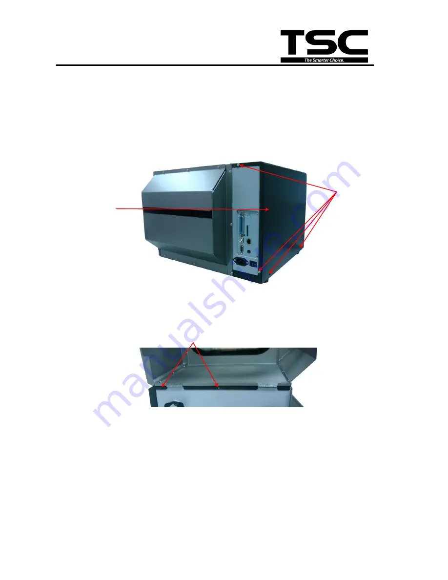
3.1 Remove Covers 


1. Remove 4 screws from printer. 


2. Open printer right side cover and remove 2 screws then close the cover. 


3. Remove the electronics cover. 

4. Remove 3 screws from each hinge. Be careful the right side cover may fall out from the 

printer. Take out the right side cover from the printer. 


Screws 

Screws 

Screws


Electronics 

cover


Right side cover


Summary of Contents for TTP-384M

Page 1: ...TTP 384M SERVICE MANUAL THERMAL TRANSFER DIRECT THERMAL BAR CODE PRINTER ...

Page 2: ...placing the LCD Panel Module 13 3 3 Replacing the Power Supply Unit 14 3 4 Replacing Multi interface Board 15 3 5 Replacing the Main Board 16 3 6 Replacing the Platen Roller Assembly 17 3 7 Replacing the Stepping Motor 18 3 8 Replacing the Printhead ASS Y 19 3 9 Replacing the Gap and Black mark Sensor Module 21 3 10 Replacing the DC Motor 23 4 TROUBLESHOOTING 25 4 1 Common Problems 25 5 MAINTENANC...

Page 3: ...M Bar Code Printer Service Manual 1 FUNDAMENTAL OF THE SYSTEM 1 1 Overview Front View 1 LED indicators 2 LCD display 3 Front panel buttons 4 Paper exit chute 5 Printer cover 6 Cutter module Optional 1 2 3 4 6 5 ...

Page 4: ...ew 1 Ribbon rewind spindle 2 Print head pressure adjustment knobs 3 Printhead 4 Ribbon sensor 5 Media sensor 6 Platen roller 7 Printhead release lever 8 Ribbon supply spindle 9 Label supply spindle 10 Media guide bar 11 Label guide 5 10 8 9 6 2 11 1 4 3 7 ...

Page 5: ...ce 9 Power switch Recommended SD card specification SD card spec SD card capacity Approved SD card manufacturer V1 0 V1 1 128 MB SanDisk Transcend V1 0 V1 1 256 MB SanDisk Transcend Panasonic V1 0 V1 1 512 MB SanDisk Transcend Panasonic V1 0 V1 1 1 GB SanDisk Transcend Panasonic V2 0 SDHC CLASS 4 4 GB V2 0 SDHC CLASS 6 4 GB SanDisk Transcend Panasonic V1 0 V1 1 microSD 128 MB Transcend Panasonic 1...

Page 6: ...Transcend V1 0 V1 1 miniSD 128 MB Transcend Panasonic V1 0 V1 1 miniSD 256 MB Transcend Panasonic V1 0 V1 1 miniSD 512 MB Transcend Panasonic V1 0 V1 1 miniSD 1 GB Transcend Panasonic V2 0 SDHC CLASS 4 miniSD 4 GB Transcend V2 0 SDHC CLASS 6 miniSD 4 GB The DOS FAT file system is supported for the SD card Folders files stored in the SD card should be in the 8 3 filename format The miniSD microSD c...

Page 7: ...ectors Main board Connector Description Remark 1 Centronics port connector J8 2 USB connector J5 3 RS 232C connector J4 4 Head open sensor connector TPH OP 5 LCD panel connector LCD PANEL 6 Multi interface board connector J11 7 Micro processor CPU 1 2 3 4 5 6 7 9 10 8 11 12 16 13 14 15 ...

Page 8: ...L 11 RFID module connector EX_SIO 12 Stepping motor connector JP14 13 Ribbon encoder sensor connector JP3 JP5 14 Power supply output 24V DC connector CN3 15 Power 24V DC connector J6 16 Printhead connector TPH_C JP2 Multi interface board Connector Description Remark 1 Main board connector 2 SD card slot 3 Ethernet RJ 45 connector 4 PS 2 connector 1 3 2 4 ...

Page 9: ...rinter Service Manual GPIO with multi interface board Optional Connector Description Remark 1 GPIO connector 2 Main board connector 3 SD card slot 4 Ethernet RJ 45 connector 5 PS 2 connector 6 GPIO power connector 2 1 4 3 5 6 ...

Page 10: ... A low on this line indicates that there are valid data at the host When this pin is de asserted the ve clock edge should be used to shift the data into the device 2 9 Data 0 7 N A In Data Bus Single directional 10 Ack N A Out A low on this line indicates that there are valid data at the Device When this pin is de asserted the ve clock edge should be used to shift the data into the host 11 Busy N ...

Page 11: ... flag 14 Ground N A GND 15 No Defined N A N A 16 17 Ground N A GND Ground 18 No Defined N A N A 19 30 Ground N A GND Ground 31 No Defined N A N A 32 Error Fault N A Out A low set by the device indicates that the reverse data is available 33 35 Ground N A GND Ground 36 No Defined N A N A Ethernet PIN CONFIGURATION 1 Tx 2 Tx 3 Rx 4 N C 5 N C 6 Rx 7 N C 8 N C PS 2 PIN CONFIGURATION 1 KBD Clock 2 GND ...

Page 12: ...10 10 TTP 384M Bar Code Printer Service Manual GPIO ...

Page 13: ...ter 2 Open printer right side cover and remove 2 screws then close the cover 3 Remove the electronics cover 4 Remove 3 screws from each hinge Be careful the right side cover may fall out from the printer Take out the right side cover from the printer Screws Screws Screws Electronics cover Right side cover ...

Page 14: ...12 12 TTP 384M Bar Code Printer Service Manual 5 Reassemble the parts in the reverse procedures ...

Page 15: ...o remove the electronics cover 2 Disconnect harness from the LCD panel module 3 Push two tabs to remove replace the LCD panel module 4 Remove 5 screws to replace LCD panel PCB ASS Y and LCD panel ASS Y 5 Reassemble the parts in the reverse procedures LCD panel module LCD panel PCB assembly PUSH PUSH Harness ...

Page 16: ...eplacing the Power Supply Unit 1 Refer to section 3 1 to remove the electronics cover 2 Disconnect 2 connectors and remove 2 screws on the power supply unit Screw Connector 3 Replace the power supply unit 4 Reassemble the parts in the reverse procedures ...

Page 17: ... to section 3 1 to remove the electronics cover 2 Remove 4 screws then take off the interface plate 3 Remove 2 screws 4 Replace the multi interface board 5 Reassemble the parts in the reverse procedures Screws Connector Screws Interface plate Multi interface board Copper pillar Copper pillar ...

Page 18: ...oard 1 Refer to section 3 1 and 3 4 to remove electronics cover and multi interface board 2 Disconnect all connectors from the main board 3 Remove 2 copper pillars and 3 screws 4 Replace the main board 5 Reassemble the parts in the reverse procedures Copper pillars Screws ...

Page 19: ... cover 2 Disengage print head lift lever 3 Remove the cutter module or lower front panel 4 Remove 4 screws from the platen holder 5 Take out the platen holder platen roller assembly and replace a new platen roller assembly 6 Reassemble the parts in the reverse procedures Screws Platen roller assembly Holder Screws ...

Page 20: ...g Motor 1 Refer to section 3 1 to remove the electronics cover 2 Disconnect the stepping motor connector from the main board 3 Remove 3 screws on the stepping motor 4 Replace the stepping motor 5 Reassemble the parts in the reverse procedures Stepping motor connector Screws ...

Page 21: ...ual 3 8 Replacing the Printhead ASS Y 1 Open the printer right side cover 2 Disengage printhead release lever 3 Remove 2 screws from the mechanism 4 Carefully disconnect 3 connectors from the printhead ASS Y 5 Replace the printhead ASS Y Screws ...

Page 22: ...printhead cable and carefully slide assembly into the print mechanism The holes of printhead assembly must align and then insert the tenons of print mechanism 7 Reassemble the parts in the reverse procedures Printhead ASS Y Printhead ASS Y Tenons Print mechanism ...

Page 23: ... printhead release lever 3 Refer to section 3 1 and 3 4 to remove electronics cover and multi interface board 4 Disconnect the gap and black mark sensor connectors from the main board 5 Remove 5 screws to take off the lower printhead mechanism Black mark sensor module connector Gap sensor module connector Screws Screws Lower printhead mechanism ...

Page 24: ...22 22 TTP 384M Bar Code Printer Service Manual 6 Replace the sensor module 7 Reassemble the parts in the reverse procedures ...

Page 25: ... to remove the electronics cover 2 Disconnect the DC motor connectors from the main board 3 Remove 3 screws at the DC motor fixing plate 4 Remove the DC motors by removing the 6 screws 5 Replace the DC motors 6 Reassemble the parts in the reverse procedures DC motor connectors Screws Screws Screws ...

Page 26: ......

Page 27: ...is installed incorrectly Supply a new ribbon roll Please refer to the steps in user s manual to reinstall the ribbon No Paper Running out of label The label is installed incorrectly Gap black mark sensor is not calibrated Supply a new label roll Please refer to the steps in user s manual to reinstall the label roll Calibrate the gap black mark sensor Paper Jam Gap black mark sensor is not set prop...

Page 28: ...rintheat Turn off the printer and plug the connector again Check if the stepping motor is plugging in the right connector Check your program if there is a command PRINT at the end of the file and there must have CRLF at the end of each command line Memory full FLASH DRAM The space of FLASH DRAM is full Delete unused files in the FLASH DRAM The max numbers of file of DRAM is 256 files The max user ...

Page 29: ...w counter clockwise to get the best print quality The release lever does not latch the printhead properly LCD panel is dark and keys are not working The cable between main PCB and LCD panel is loose Check if the cable between main PCB and LCD is secured or not LCD panel is dark but the LEDs are light The printer initialization is unsuccessful Turn OFF and ON the printer again Initialize the printe...

Page 30: ... is plugged in the right connector Power and Error LEDs are blinking fast Power switch OFF and ON too fast Turn off the printer and wait all LEDs are dark and turn on the printer again Wrinkle Problem Printhead pressure is incorrect Ribbon installation is incorrect Media installation is incorrect Print density is incorrect Media feeding is incorrect Make sure the label guide touch the edge of the ...

Page 31: ...nter Part Method Interval Print Head 1 Always turn off the printer before cleaning the print head 2 Allow the print head to cool for a minimum of one minute 3 Use a cotton swab Head cleaner pen and 100 ethanol to clean the print head surface Clean the print head when changing a new label roll Platen Roller 1 Turn the power off 2 Rotate the platen roller and wipe it thoroughly with 100 ethanol and ...

Page 32: ...acuum As needed Note Do not touch printer head by hand If you touch it careless please use ethanol to clean it Please use 100 Ethenol DO NOT use medical alcohol which may damage the printer head Regularly clean the print head and supply sensors once change a new ribbon to keep printer performance and extend printer life ...

Page 33: ...Replacing the printhead assembly Camille 2009 2 20 Modify section 3 8 Replacing the printhead assembly Camille 2009 3 16 Modify section 1 1 Recommended SD card specification Camille 2011 1 25 Modify TSC address Camille 2011 4 8 Modify section 2 2 Camille 2011 5 10 Add section 3 10 Replacing the DC motor Camille ...

Page 34: ......

Page 35: ...g 1st Rd Wujie Township New Taipei City 23141 Taiwan R O C Yilan County 26841 Taiwan R O C TEL 886 2 2218 6789 TEL 886 3 990 6677 FAX 886 2 2218 5678 FAX 886 3 990 5577 Web site www tscprinters com E mail printer_sales tscprinters com tech_support tscprinters com TSC Auto ID Technology Co Ltd ...

Reviews: