3.
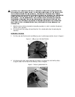
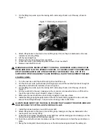
On the lifting loop side, open the locking latch and swing it back out of the way, shown in
Figure 5.
Figure 5: Removing Locking Latch
4.
Attach lifting hooks to the drive arm and lifting loop. Ensure they are balanced so the reel
remains level during lifting.
5.
Lift the reel straight up.
6.
Remove the bronze bearing from reel shaft.
7.
Loosen the nuts on the lifting loop and remove it from reel shaft.
8.
Remove reel shaft from reel.
WARNING/CAUTION! NEVER ATTEMPT TO INSTALL OR REMOVE A REEL UNLESS THE
DRIVE ARM LOOP IS IN THE UPRIGHT POSITION. IF THE REEL SHAFT PIN IS REMOVED
WITH THE DRIVE ARM IN ANY OTHER POSITION, THE REEL MAY FALL OUT OF ITS
SUPPORTED POSITION AND MAY CAUSE PERSONAL INJURY OR EQUIPMENT DAMAGE.
LOADING A REEL
1.
Turn the reel drive until the shaft coupling drive teeth face up.
2.
On the drive arm side, pull ball lock pin straight up and pull the reel shaft pin back enough to
allow the reel shaft to be installed, shown in Figure 4.
3.
On the lifting loop side, open the locking latch and swing it back out of the way, shown in
Figure 5.
4.
Put the reel shaft in the reel, making sure the conductor or rope will wind on or off from the
top of the reel in the correct direction, shown in Figure 2.
5.
Make sure the reel shaft drive pins are fully engaged in reel drive holes.
6.
Install the lifting loop tight against side of the reel to hold it firmly against the drive arm and
keep it from sliding sideways. Torque nuts on locking collar to 200 ft-lbs.
ALWAYS MAKE SURE THAT THE REEL IS PUSHED TIGHT AGAINST THE DRIVE ARM AND
HELD SECURELY BY LIFTING LOOP/LOCKING COLLAR.
7.
Install the bronze bearing on end of the reel shaft.
8.
Attach lifting hooks to the drive arm and lifting loop, making sure they are balanced so the
reel remains level during lifting.
9.
Lower the reel in place engaging the reel shaft drive with its mating part and making sure the
bronze bearing locates in the bearing support.
10. Push the reel shaft pin back into place and insert the ball lock pin to hold the reel shaft pin in
place.
11. Swing the locking latch back into place over the bronze bearing and insert the safety pin.
Summary of Contents for T50 BWRC
Page 11: ......
Page 12: ......
Page 24: ......
Page 25: ......
Page 26: ......
Page 27: ......
Page 28: ......
Page 29: ......
Page 30: ......
Page 31: ......
Page 32: ......
Page 33: ......
Page 34: ......
Page 35: ......
Page 36: ......
Page 37: ......
Page 38: ......
Page 43: ...www dexteraxle com OPERATION MAINTENANCE SERVICE MANUAL 600 8 000 lb Axles Related Components ...
Page 125: ...Service Record Date Service Performed Mileage ...
Page 126: ...Service Record Date Service Performed Mileage ...
Page 127: ...Service Record Date Service Performed Mileage ...


