background image

3:Operation 

    23 


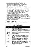
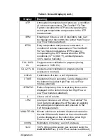
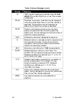
Table 3. Screen Displays (cont.) 

Display 

Meaning 

ATP 

Atmospheric temperature and pressure: a condition 
of volume measurement. The Certifier

®

 FA Test 

System calculates the ATP value by applying the 
actual gas temperature and pressure to the STP 
measurement. 

BPM 

Breaths per minute: a unit of respiratory rate. Can 
be displayed on the bottom line (either High Flow or 
Low Flow module attached). 

BTPS 

Body temperature and pressure, saturated: a 
condition of volume measurement. The Certifier® 
FA Test System calculates a BTPS value by 
compensating the STP measurement for BTPS 
conditions (37 °C (98.6 

F), ambient pressure, 

100% relative humidity). 

CAL 100% 

O

2


Oxygen sensor calibration in progress (during 
exposure to 100% O

2

). 

CAL 21% O

2


Oxygen sensor calibration in progress (during 
exposure to room air). 

cmH

2

Centimeters of water: a unit of pressure. 

I TIME 

Inspiratory time (in seconds). Can be displayed on 
the bottom line (either High Flow or Low Flow 
module attached). 

I:E RATIO 

Ratio of inspiratory time to expiratory time, can be 
displayed on the bottom line (when High Flow or 
Low Flow module is attached). 

Liter: a unit of volume. 

LPM 

Liters per minute: a unit of flow. The Certifier

®

 FA 

Test System calculates the LPM value by applying 
the actual gas temperature and pressure to the 
SLPM measurement. 

MINUTE VOL  Minute volume: an estimate of exhaled volume for 

the next 60 seconds, based on the current breath. 
Can be displayed on the bottom line (when High 
Flow or Low Flow module is attached). 

mmHg 

Millimeters of mercury: a unit of pressure. 

N

2

100% nitrous oxide supply gas, selected using the 

GAS SELECT

 key (if Low Flow module is attached). 

Summary of Contents for CERTIFIER FA

Page 1: ...CERTIFIER FA TEST SYSTEM OPERATOR S MANUAL P N 1980436 REVISION L FEBRUARY 2017 ...

Page 2: ......

Page 3: ...ATOR S MANUAL P N 1980436 REVISION L FEBRUARY 2017 U S INTERNATIONAL TSI Instruments Ltd UK Sales and Customer Service Sales and Customer Service 800 874 2811 1 651 490 2811 44 0 1494 459200 Fax Fax 1 651 490 3824 44 0 1494 459700 ...

Page 4: ......

Page 5: ...rranty on finished goods manufactured by others or on any fuses batteries or other consumable materials Only the original manufacturer s warranty applies e This warranty does not cover calibration requirements and seller warrants only that the instrument or product is properly calibrated at the time of its manufacture Instruments returned for calibration are not covered by this warranty f This war...

Page 6: ...SMANTLING OR REINSTALLATION COSTS OR CHARGES No Action regardless of form may be brought against Seller more than 12 months after a cause of action has accrued The goods returned under warranty to Seller s factory shall be at Buyer s risk of loss and will be returned if at all at Seller s risk of loss Buyer and all users are deemed to have accepted this LIMITATION OF WARRANTY AND LIABILITY which c...

Page 7: ...8 Peak Pressure 18 3 4 9 Peep Pressure 18 3 4 10 Breath Rate 18 3 4 11 I E Ratio 18 3 4 12 I Time 19 3 4 13 Absolute Pressure 19 3 4 14 Oxygen Concentration 19 3 5 Required Pre test Calibrations 20 3 5 1 Low Pressure Transducer Zero Calibration 20 3 5 2 Oxygen Sensor Calibration 20 3 6 Breathing Cycles and Trigger Levels 21 3 6 1 Inhalation and Exhalation Timing 21 3 6 2 Flow Trigger Levels 21 3 7...

Page 8: ...w Module 7 Figure 4 Connecting the Bacteria Filters to the Flow Modules 8 Figure 5 Attaching Pressure Tubing to the High Flow Module 9 Figure 6 Attaching the Oxygen Sensor to the High Flow Module 10 Figure 7 Installing a Flow Module into the Test Circuit 11 Figure 8 Certifier FA Test System Installed in an Oxygen Concentrator Circuit 12 Figure 9 Controller Module Keypad 14 List of Tables Table 1 C...

Page 9: ...e Measures air or 100 oxygen O2 over a range of flows from 0 to 300 standard liters per minute SLPM Low Flow module Measures air 100 O2 or 100 nitrous oxide N2O over a range of flows from 0 01 to 15 SLPM with greater accuracy than the High Flow module at low flow rates Oxygen sensor Used with the High Flow module allows the High Flow module to measure O2 concentration and other measurements for an...

Page 10: ... the Certifier FA Test System Use only factory approved parts and procedures to service the device CAUTION To avoid inaccurate test readings do not obstruct tubing or inlet or exhaust ports and always use dry gas To avoid damage to the Certifier FA Test System components always use bacteria filters upstream of the flow modules and always cap flow module ports when not in use TSI flowmeters are not...

Page 11: ...s from the shipping container Check the individual parts against the packing list and notify TSI immediately if anything is missing or damaged Table 1 summarizes the Certifier FA Test System components and part numbers shown in Figure 2 Figure 2 Certifier FA Test System Parts ...

Page 12: ...19289 1 5 Adapter 15 mm ID x 22 mm OD 1102093 1 6 Airway pressure fitting with screen 1611330 1 7 Adapter 22 mm x 6 mm for interfacing High Flow module to Low Flow filter for use with oxygen concentrator 1102091 2 8 Pressure tubing 1 8 in ID x 1 4 in OD x 48 in length silicone 3002053 1 9 Mounting bracket includes mounting bracket screws and Velcro strap 1040044 1 10 Pocket driver used to remove i...

Page 13: ...l the controller module battery cover 3012034 1 11 AA batteries not shown NA 4 12 Certifier FA Test System Operator s Manual not shown 1980436 1 High Flow module kit optional part no 4076 2 High Flow module 4071 1 3 Bacteria filter 22 mm x 22 mm male female for use with High Flow module single use 1602341 1 5 Adapter 15 mm ID x 22 mm OD 1102093 1 6 Airway pressure fitting with screen 1611330 1 7 A...

Page 14: ...ional part no 4073 15 Oxygen sensor 2917019 1 16 Threaded tee 1313118 1 17 Cable 8 in length 1303741 1 Other accessories optional 18 Hard shell carrying case holds Certifier FA Test System and accessories 1319288 1 1 2 Glossary These labels terms and symbols appear on the Certifier FA Test System Refer to manual see Certifier FA Test System Operator s Manual for important information Safety approv...

Page 15: ...ways use bacteria filters upstream of the flow modules and always cap flow module ports when not in use 1 Connect the controller module to a flow module Figure 3 To remove the cable pull its locking connector not the cable from the controller module Controller module Flow module Figure 3 Connecting the Controller Module to a Flow Module ...

Page 16: ...ng the filter s flow arrow with the direction of the flow ensuring that the filter s inlet indicator labeled INLET I or other faces upstream of the flow module or that the outlet indicator label Patent side Outlet or other faces towards the flow module Controller module High Flow module note flow direction Low Flow module note flow direction High Flow filter Low Flow filter Figure 4 Connecting the...

Page 17: ...essure tubing Figure 5 Attach one end of the pressure tubing to the low pressure port on the flow module and the other to the pressure port in the circuit Pressure tubing High Flow module Figure 5 Attaching Pressure Tubing to the High Flow Module ...

Page 18: ...e and oxygen sensor Turn the cable collar to secure the cable to the oxygen sensor Use the threaded tee to install the oxygen sensor into the circuit The oxygen sensor can only connect to the High Flow module High Flow module Threaded tee Oxygen sensor Oxygen sensor cable Figure 6 Attaching the Oxygen Sensor to the High Flow Module ...

Page 19: ...he flow module into the test circuit Figure 7 Figure 8 Align the flow direction of the flow module and filter with the direction of flow through the circuit Ventilator Figure 7 Installing a Flow Module into the Test Circuit ...

Page 20: ...12 2 Setup Oxygen Concentrator Figure 8 Certifier FA Test System Installed in an Oxygen Concentrator Circuit ...

Page 21: ...e oxygen sensor is installed the controller module will display a symbol 4 Default measurements displayed High Flow module flow top line low pressure bottom line Low Flow module flow top line respiratory rate bottom line CAUTION To ensure accurate measurements wait about one minute for the Certifier FA Test System to warm up If environmental conditions have changed significantly more time may be n...

Page 22: ...t shown on the top line of the display Bottom line select Selects the measurement shown on the bottom line of the display ON Off Turns the system on I or off O DISPLAY UNITS Selects the unit of measure for measurements GAS SELECT Selects the supply gas type for the Certifier FA Backlight on off Turns the controller module display backlight on or off 3 3 Displaying Test Measurements Follow these st...

Page 23: ...ld flow calculated from the last three breaths is updated at each breath and then is applied to the following breath Breath measurement displays begin after two full breaths CAUTION To avoid damage to the Certifier FA Test System components always use bacteria filters upstream of the flow modules and always cap flow module ports when not in use 3 4 Measurements Measurements on Top Line of Display ...

Page 24: ...L can be selected using the DISPLAY UNITS key See Section 3 7 Display Information for definitions of these units of measure For the High Flow module air O2 and air O2 mixture can be selected using the GAS SELECT key For the Low Flow module air O2 and N2O can be selected using the GAS SELECT key NOTE A valid flow cycle must occur for this value to be displayed See Section 3 6 Breathing Cycles and T...

Page 25: ... sensor is attached to the High Flow module the oxygen concentration O2 can be displayed on the top line of the control module display Oxygen concentration can also be displayed on the bottom line of the display see Section 3 4 14 Daily calibrations need to be done on the oxygen sensor See Section 3 5 2 for instructions on oxygen sensor calibration NOTE The symbol will appear on the display when t...

Page 26: ...ory pressure PEEP from the low pressure port of the High Flow module can be displayed on the bottom line of the control module display Select units of PEEP cmH2O or PEEP mmHg by pressing and holding the DISPLAY UNITS key for three seconds For best results check the zero on the low pressure transducer before measurements See Section 3 5 1 for instructions on zeroing the pressure transducer NOTE A v...

Page 27: ...A s I time will not match the vents I time 3 4 13 Absolute Pressure The absolute pressure in the flow tubes can be displayed on the bottom line of the control module display in units of mmHg NOTE For distinguishing absolute pressure from low pressure the resolution for absolute pressure measurement is displayed in a resolution of 1 mmHg and low pressure Section 3 4 7 is displayed in a resolution o...

Page 28: ...calibration is complete NOTE The barometric pressure transducer does not require a zero calibration 3 5 2 Oxygen Sensor Calibration Follow these steps daily and following an altitude change or sensor replacement to calibrate the oxygen sensor 1 Power up the Certifier FA Test System with the High Flow module and oxygen sensor attached then allow about one minute to warm up The oxygen sensor symbol ...

Page 29: ...trigger level the flow rate must remain below the trigger level for at least 0 25 milliseconds otherwise this period is included in the inhalation cycle If testing of ventilator pressure modes is needed a test lung must be used to ensure that a long enough flow delivery time is generated If there is not enough volume in the breathing circuit the pressure can be generated in less than 0 25 millisec...

Page 30: ...s the new trigger level will be set and the interface module will return to displaying volume NOTE The default value of 20 auto trigger is restored once the controller module is turned off 3 7 Display Information Table 3 describes information that can appear on the controller module screen Table 3 Screen Displays Display Meaning An out of range measurement Oxygen sensor symbol indicates presence o...

Page 31: ...0 O2 CAL 21 O2 Oxygen sensor calibration in progress during exposure to room air cmH2O Centimeters of water a unit of pressure I TIME Inspiratory time in seconds Can be displayed on the bottom line either High Flow or Low Flow module attached I E RATIO Ratio of inspiratory time to expiratory time can be displayed on the bottom line when High Flow or Low Flow module is attached L Liter a unit of vo...

Page 32: ... S Stacked volume a cumulative volume measurement for consecutive breaths The top line shows the cumulative volume and the bottom line shows the number of consecutive breaths SEC Seconds a unit of time for I TIME measurements SLPM Standard liters per minute a unit of flow The Certifier FA Test System measures flows in SLPM Standard conditions are defined as 21 1 C 70 F at 101 3 kPa 14 7 psia STP S...

Page 33: ...isplayed even though controller module is on Flow module isn t connected to controller module Connect flow module to controller module is shown on display Measurement is out of range Check range for displayed measurement and only make measurements within that range Flow rate does not read zero when no gas flowing Especially when set to N2O Meter was not purged with gas displayed on the controller ...

Page 34: ...ached Wait for at least two consecutive full breaths to be supplied to the flow module Ensure that flow is supplied as a breathing waveform Manually set flow trigger level Certifier FA cannot measure shorter than 0 25 millisecond flow delivery Use a test lung so that at least 0 25 milliseconds of flow delivery is generated to generate pressure Can t change measurement units Measurement isn t displ...

Page 35: ... for calibration Flow of 100 oxygen is too low Verify that calibration gases are 21 oxygen and 100 oxygen and repeat calibration Increase flow of 100 oxygen to at least 5 SLPM and repeat calibration Oxygen sensor calibration fails 21 oxygen and or 100 oxygen not supplied for calibration Oxygen sensor is expired Verify that calibration gases are 21 oxygen and 100 oxygen and repeat calibration Repla...

Page 36: ...28 4 Troubleshooting This page intentionally left blank ...

Page 37: ...year of normal operation if use begins before the expiration date Replace the oxygen sensor every year of normal use or if the sensor cannot be calibrated or sensor readings are erratic 5 3 Cleaning as required Table 5 summarizes recommended cleaning methods for Certifier FA Test System components Table 5 Cleaning Recommendations Component Cleaning Controller module Flow modules Carrying cases Oxy...

Page 38: ...y calibration Follow the steps in Section 5 5 to return Certifier FA Test System flow modules for factory calibration 5 5 Return Procedure Follow these steps to return Certifier FA Test System flow modules for factory calibration 1 Contact one of the following offices to make service arrangements and obtain a Return Material Authorization RMA number or use our online RMA form at www tsi com 2 Pack...

Page 39: ... decreasing linearly to 15 to 50 relative humidity at 40 C Storage 40 to 70 C 40 to 158 F at 10 to 95 relative humidity Atmospheric Pressure Operating 57 1 to 106 kPa 8 28 to 15 37 psia Storage 50 to 106 kPa 7 25 to 15 37 psia Conditions Indoor Use Operating Altitude up to 4000 m 13 000 ft Pollution degree I or II 6 3 Power Battery life 15 to 20 hours Battery type Four commercially available AA ba...

Page 40: ... whichever is greater Minute Volume Range 0 to 99 00 L STP 0 to 9 999 L STP Accuracy 7 of reading 7 of reading Stacked Volume Range 0 to 99 00 L STP 0 to 9 999 L STP Accuracy Air and oxygen 2 of reading plus 0 020 L STP Air oxygen mixtures 4 of reading plus 0 020 L STP Air and oxygen 2 of reading or 0 010 L STP whichever is greater Nitrous oxide 4 of reading or 0 010 L STP whichever is greater Ins...

Page 41: ...curacy de rating 0 075 of reading per 1 C 1 8 F away from 21 1 C 70 F 0 015 of reading per 1 03 kPa 0 15 psia above 101 3 kPa 14 7 psia 0 022 of reading per 1 03 kPa 0 15 psia below 101 3 kPa 14 7 psia 0 07 of reading per 1 relative humidity above 30 relative humidity 6 5 Calibration Requirements Flow modules Factory calibration every year for normal use under normal conditions using the filter s ...

Page 42: ...nformation USA Tel 1 800 874 2811 UK Tel 44 149 4 459200 France Tel 33 1 41 19 21 99 Germany Tel 49 241 523030 India Tel 91 80 67877200 China Tel 86 10 8219 7688 Singapore Tel 65 6595 6388 P N 1980436 Rev L Copyright 2017 by TSI Incorporated Printed in U S A ...

Reviews: