OPERATOR’S MANUAL
96 / CALIBRATIONS
ISO
6
Version 4 UL 2_3 Manual
6011258 Rev C
4.
Put the transmission in “park” or in a locked, neutral position.
5. Engage hydraulic system.
6. Run engine at normal operating RPM until hydraulic fluid is
at normal operating temperature.
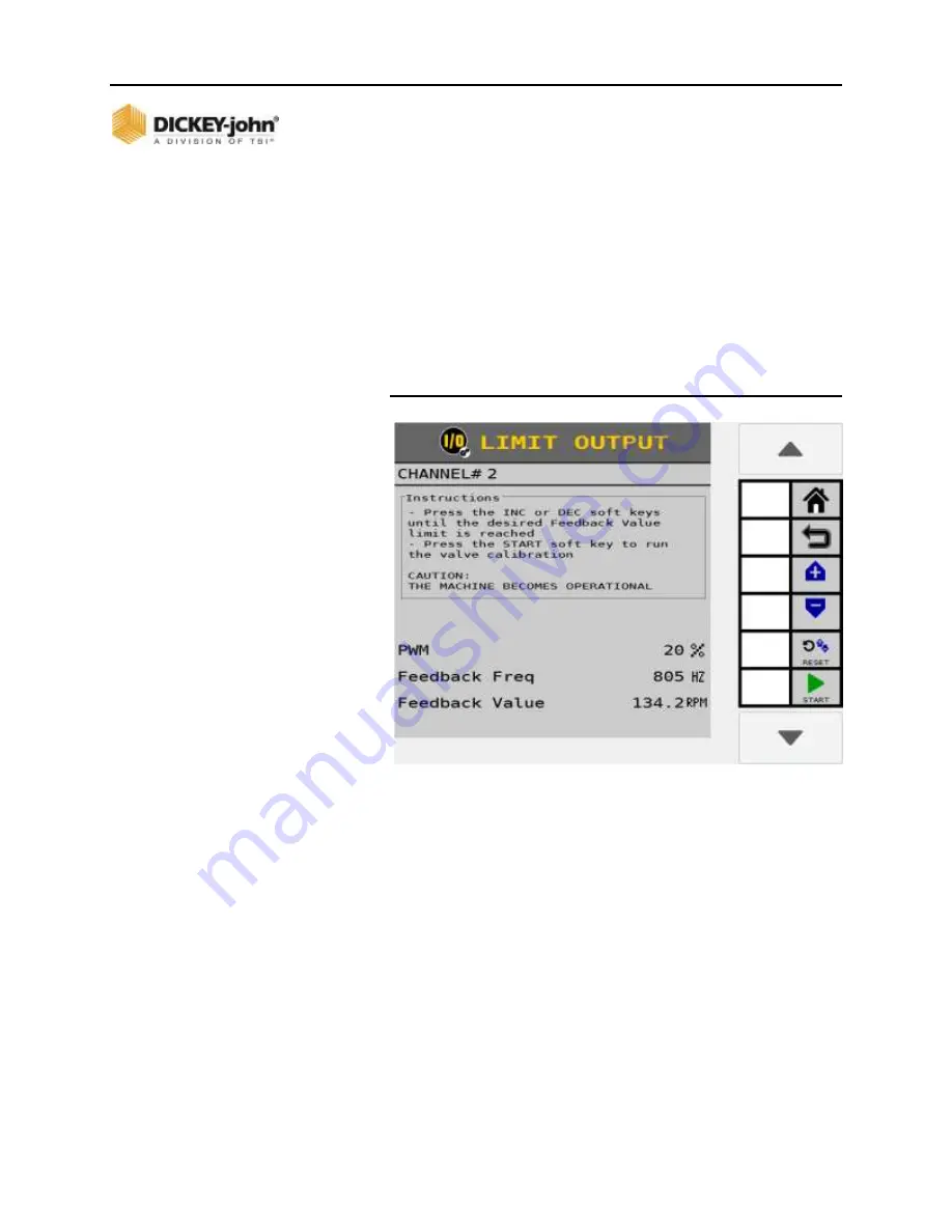
7. To change the valve position, press the Increment or
Decrement buttons repeatedly until the desired maximum
output value is reached.
8. Press the
START
button and the valve calibration
immediately begins.
The calibration runs using the new max flow value.
Figure 65
Limit Output Screen


