OPERATOR’S MANUAL
162 / OPERATION
ISO
6
Version 4 UL 2_3 Manual
6011258 Rev C
WORK SCREEN FUNCTIONS
The Work Screen in Work Mode displays the various instruments
that were selected at the Instruments screen. A total of four
Work Screens are accessible during Work Mode if four
screens are setup.
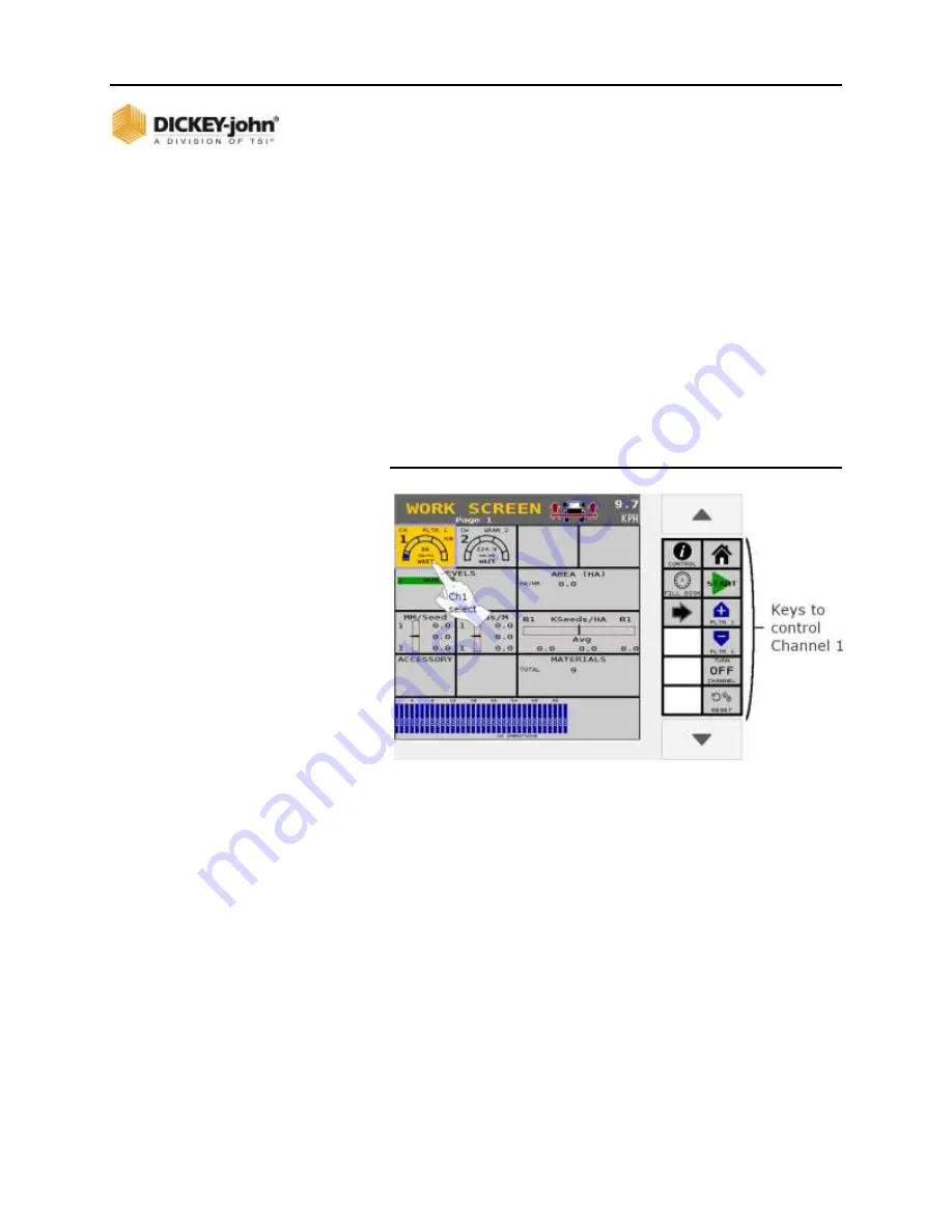
In Work Mode, buttons appear on the right side of the screen
based on the main instruments selected on the Instruments
screen. (Virtual terminals may vary on button locations) (Figure
122) shows channel 1 control instrument selected. All buttons on
the right side of the screen affect channel 1. When another
instrument is selected, these buttons are replaced with the
buttons relative to the newly selected instrument.
Figure 122
Selecting Channel 1 Instrument
READING THE CONTROL INSTRUMENT
The status ball represents the actual applied rate of material.
The arched status bar contains 5 sections. The middle
section is the ideal applied rate/target rate (Green). Section
percent ranges vary depending on instrument set up. See
Control Instrument Setup for more information.
The rates to the left of the ideal range are under applying
rates below the target limit parameters.
The rates to the right of the ideal range are over applying
rates above the target limit parameters.
The target rate displays as a constant value. Application
rates appear in black within target rate range. Rate values
appear in red when outside of target rate limit parameters.


