


29
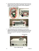
7. Remove power supply (if applicable).
8. Remove Enclosure Heater (if applicable).
9. Package enclosure to prevent damage.
10. Package accessories to prevent damage.
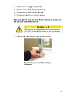
Removing Photometer from Environmental Enclosure
for Service or Replacement
W A R N I N G
Disconnect all cables before removing photometer
from Environmental Enclosure to prevent damage.
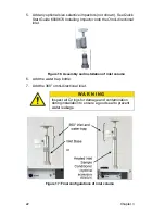
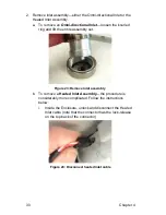
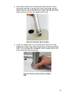
1. Unscrew the second knurled ring from the bottom.
Figure 22: Unscrew second knurled ring
from bottom
Summary of Contents for DUSTTRAK 854030
Page 2: ......
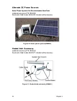
Page 12: ...2 Chapter 1 Figure 3 Power Strip ...
Page 18: ...8 Chapter 2 This page intentionally left blank ...
Page 36: ...26 Chapter 3 This page intentionally left blank ...
Page 48: ...38 Chapter 4 This page intentionally left blank ...
Page 52: ...42 Chapter 5 This page intentionally left blank ...
Page 54: ...44 Chapter 6 This page intentionally left blank ...
Page 58: ......


