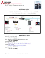

Tsino-Dynatron Electrical Technology (Beijing) Co., Ltd.
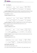
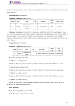
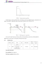
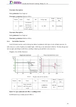
When the motor can not follow the acceleration or deceleration of a position or velocity command, the
following lagged value will increase, resulting in alarms for excessive position or velocity following errors. Please
keep the acceleration or deceleration of a position or velocity command within a range feasible for the motor to
follow, or increase the position or velocity following error threshold.
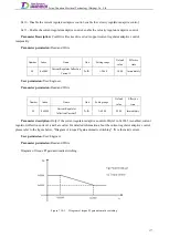
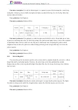
Regulator Adjustment
8.2
This section mainly introduces the adjustment of various regulators in the servo system to improve the overall
dynamic stability of the system. A proportional regulator is used to proportionally reflect the system deviation.
Once the system has a deviation, the proportional regulator will work immediately to reduce the deviation. A large
proportional action can accelerate the adjustment to reduce errors. However, an overlarge proportional action will
make the system less stable, or even instable.
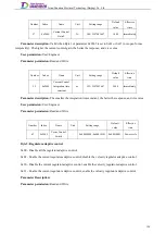
The integration regulator is used to eliminate the steady-state errors of the system to improve the
in-discrimination degree. The integration regulator works as long as there is an error. When there is no error, the
integration regulator stops and outputs a constant. The effect of the integration action depends on the integration
time constant Ti. The smaller the Ti, the stronger the integration action, and vice versa. If an integration action is
too strong, it can lower the system stability and slow down the dynamic response.
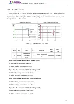
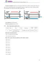
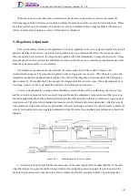
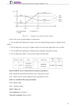
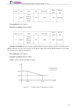
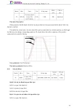
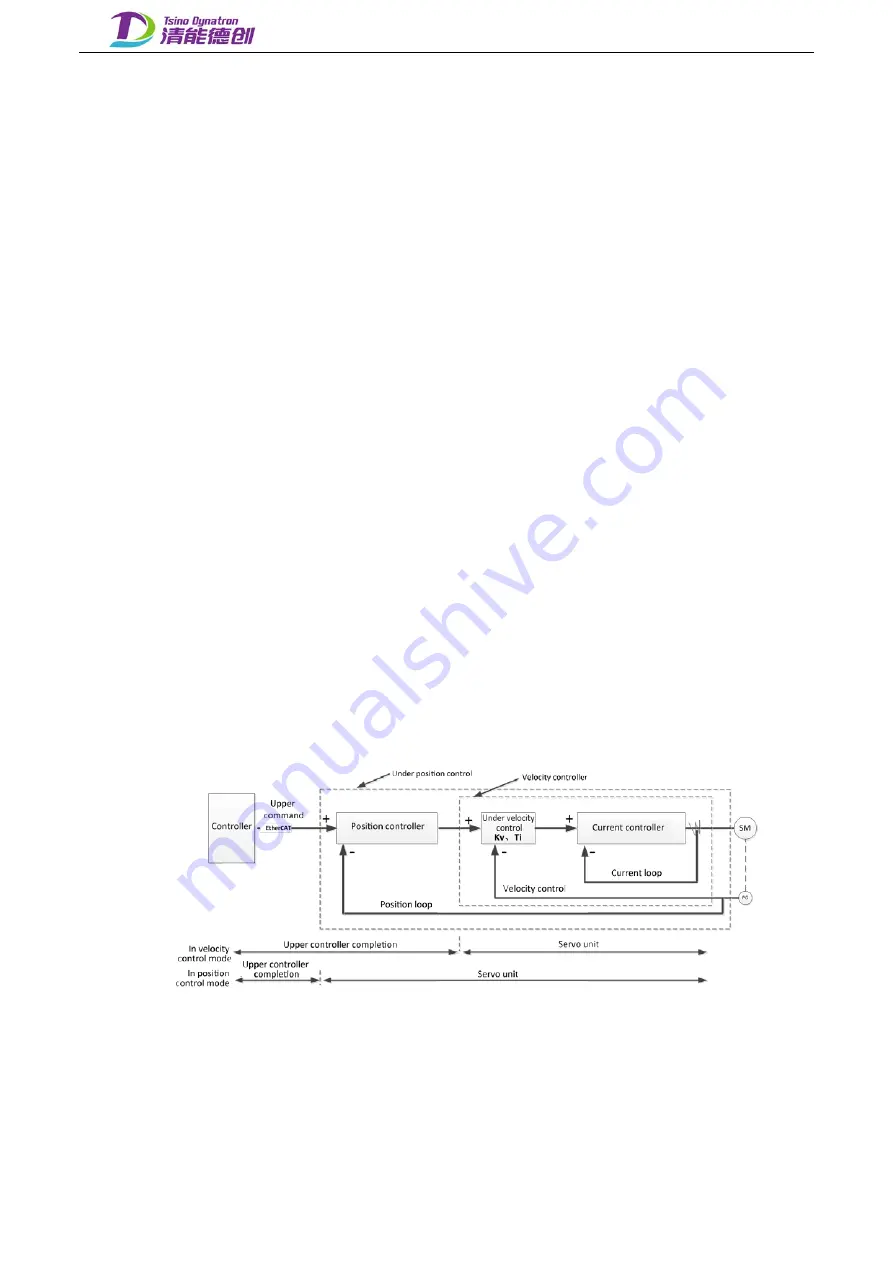
A servo system generally consists of three feedback systems, which are the position loop, the velocity loop
and the current loop respectively from outside to inside. During the adjustment, responsiveness of the inner loop
should be higher than that of the outer loop. Failure to follow this principle will lead to vibration or a poor system
responsiveness. The current loop regulator parameters are only related to the motor parameters. After the current
loop parameters of the same motors are determined, if there is no change on loads, it is only necessary to adjust the
velocity loop and position loop regulator parameters, while the current loop regulator parameters are no need to be
adjusted.
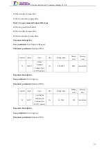
Figure 8.2-1.
Block diagram of the servo system
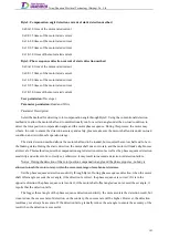
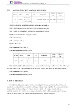
a. According to the principle that the responsiveness of the inner loop should be higher than that of the outer
loop, the velocity loop gain should be increased before increasing the position loop gain. If only the gain of the
position loop is increased, it may cause the velocity command vibration, resulting in delay of positioning time.
187
Summary of Contents for EtherCAT CoolDrive RC Series
Page 1: ...Updated on Update summary Updated version Version number D3 ...
Page 17: ...Tsino Dynatron Electrical Technology Beijing Co Ltd Dimension Drawing of RC3 2 3 2 7 ...
Page 18: ...Tsino Dynatron Electrical Technology Beijing Co Ltd Dimension Drawing of RC4 2 3 3 8 ...
Page 19: ...Tsino Dynatron Electrical Technology Beijing Co Ltd 9 ...
Page 20: ...Tsino Dynatron Electrical Technology Beijing Co Ltd Dimension Drawing of RC6 2 3 4 1 ...