4
2
Description
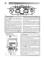
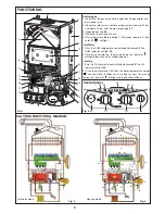
Location of components
1. - Air pressure switch
2. - Steel chassis complete with expansion vessel
3. - Flue hood with fan
4. - Main heat exchanger
5. - Combustion chamber
6. - Multi- gas burner assembly comprising ignition and
ionisation electrodes
7. - Pump
8. - Central heating eating flowswitch
9. - Automatic air separator and automatic vent
10. - DHW detector
11. - Sealed chamber
12. - Electrical box
13. - Overheat safety cutout
14. - Gas valve assembly
15. - TSS ® (mini cylinder)
16. - Central heating control thermistor
17. - Three way valve
18. - TSS® control thermistor
19. - Domestic hot water flowswitch
20. - Secondary heat exchanger
21. - DHW pressure relief valve
22. - Taps bracket
23. - Two position Selector switch
OFF
«
O
»
ON
«
I
»
24. - Domestic hot water temperature adjustment
25. - Heating flow temperature control knob
26. - Heating temperature indicator lights
27. - Green indicator - Power ON
28 - Orange indicator - Burner ON
29. - Red indicator - Lock out / flame failure
30. - Reset button
31. - Pressure gauge
32. - DHW mode indicator
33. - Heating mode indicator
K. - flue kit fixing point (refer to kit manual)
15
16
17
22
19
10
18
8
21
Fig. 2
9
2
1
3
4
5
6
7
12
13
11
14
Fig. 1
K
I
reset
Fig.3
32
31
30
23
25
33
26
24
27
28
29
20
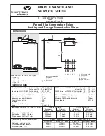
Summary of Contents for Calydra Comfort 100 Nat
Page 48: ...110...

