background image

B

CAL

YDRA COMFOR

T

107

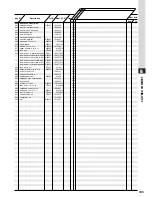
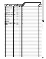
Description

Key N°

Manf. Pt. N°

Type

G.C N°

CALYDRA

COMFORT

80

FF

Manf. date

from      to

1000

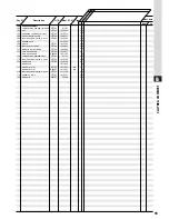
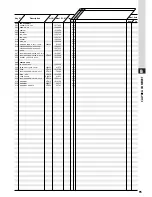
FLUE CONNECTION               

1001

HORIZONTAL FLUE KIT D60-100   

1303383

..

1002

V./HORIZONTAL FLUE KIT D60-100

1306054

..

1003

VERTICAL FLUE KIT D80-125     

1304703

..

1004

VERTICAL FLUE KIT D60-100     

1309229

..

1005

DOUBLE-FLOW FLUE KIT D80-80   

1304704

..

1011

GASKET (/ Flue bend turret)   

1300258

..

1012

FLUE BEND TURRET ASSY         

1306699

..

1013

SLEEVE D:100                  

61310308

..

1014

FLUE DUCT SECOND SECTION      

1306700

..

1015

AIR DUCT                      

1300298

..

1016

SEALING RING TRIM             

366995

62079

..

1017

SLEEVE JOINT                  

264357

62181

..

1018

SCREW CLX M 5-20              

1017600

..

1019

GASKET                        

1303250

..

1020

RESTRICTOR D:82               

1304754

..

RESTRICTOR D:84               

1305420

..

RESTRICTOR D:75               

1306276

..

RESTRICTOR D:78               

1307339

..

RESTRICTOR D:80               

1307846

..

RESTRICTOR D:79               

1308126

..

1023

VERTICAL ADAPTATER            

1305982

..

1024

FLUE DUCT SECOND SECTION      

1300300

..

FF

CALYDRA

COMFORT

100

Summary of Contents for Calydra Comfort 100 Nat

Page 1: ...Fanned Flue system Installation and Operating instructions 1 2 3 0 4 bar 1 2 3 0 4 bar c Calydra comfort 80 Calydra comfort 100 C C Manufactures N Model Type Gas Council N 200906789037 31 Calydra com...

Page 2: ...onal warrenty helpline 0870 243 0224 Advice on installation or servicing can also be obtained by contacting the Chaffoteaux Customer Services Department at Telford CUSTOMER SERVICES DEPARTMENT Tel 019...

Page 3: ...n is able to provide the user with hot water immediately at the outlet of the appliance and stable temperatures at both extremely low flow rates or when several taps are opened together The TSS is a 5...

Page 4: ...trol thermistor 17 Three way valve 18 TSS control thermistor 19 Domestic hot water flowswitch 20 Secondary heat exchanger 21 DHW pressure relief valve 22 Taps bracket 23 Two position Selector switch O...

Page 5: ...inal in mbar 20 20 Nominal in in wg 8 8 Burner pressure Nominal in mbar 11 12 8 Nominal in in wg 4 4 5 1 Burner injector diameter Natural gas G20 in mm 1 23 1 28 Calydra comfort 80 100 PROPANE L P G G...

Page 6: ...ydra comfort 80 37 5kg Calydra comfort 100 38 5kg Lift weight Calydra comfort 80 31 5 kg Calydra comfort 100 32 5kg Tails diameter I Safety valve outlet 15 mm J Heating flow 22 mm K D H W flow 15 mm L...

Page 7: ...is given to a demand for hot water This will interrupt the central heating for the duration of hot water delivery or recovery of the mini cylinder When the boiler has been in standby in Hot Water Mode...

Page 8: ...00 mm J From a surface facing the terminal 600 mm K From a terminal facing the terminal 1200 mm L From an opening in the car port into the dwelling1200 mm M Vertically from a terminal on the same wall...

Page 9: ...ury Ltd for first installation tails kit or to replace existing boilers such as old Chaffoteaux et Maury models Before fitting the tails onto the connecting bracket please check the correct location o...

Page 10: ...ry set at 3 minutes JP3 the spade connector fig 14 allows the gas rate to be reduced to 1 3 performance by positionning spade across pins as shown fig 14 Full performance across pins as shown fig 14 A...

Page 11: ...ght from the manufacturers of water treatment products such as Betz Dearborn Ltd Foundry Lane Widnes Cheshire WA8 8UD Tel 0151 424 5351 Fernox Manufacturing Britannica Works Clavering Essex CB11 4QZ T...

Page 12: ...position I Turn the boiler thermostat to maximum 25 fig 17 The boiler will light Allow the boiler to heat system Check the inlet gas pressure working pressure while boiler is operating in hot water m...

Page 13: ...hot water while the heating is on it is only necessary to turn on a hot tap The heating will be interrupted momentarily while the hot water is being delivered The boiler will switch back automatically...

Page 14: ...times The clock uses a 24hours system e g 8 8 00 am and 18 6 00 pm ON periods are set by sliding all tappets between the ON time and the OFF time to the outer edge of the dial The tappets remaining a...

Page 15: ...detection without burner working Besides freezing pump Besides freezing burnerr Lack of water circulation Primary water circulation defect Thermistor sanitary open Thermistor sanitary bypassed Thermi...

Page 16: ...epts no liability for any errors or omission in the information contained in this document Manufacturer Chaffoteaux Maury France Commercial subsidiary MTS GB Limited MTS Building Hughenden Avenue High...

Page 17: ...lydra comfort 80 Calydra comfort 100 Maximum Minimum Maximum Minimum power 25 9 kW power 9 5 kW power 31 1 kW power 9 5 kW Natural gas G 20 at 20 mbar 2 74 m3 h 1 00 m3 h 3 29 m3 h 1 00 m3 h Butane ga...

Page 18: ...stion chamber made of alumi nium coated steel with 4 ceramic fibre panels to provide heat insulation 6 Multigas burner comprising 6a 16 burner head 6b Manifold 6c 2 Ignition electrode 6d Ionization el...

Page 19: ...rn on a hot water tap the orange burner on indicator will light 28 and the water will become hot Heating 1 Turn the CH thermostat control knob clockwise 25 The CH indicator will light 33 2 If the room...

Page 20: ...nd the pump stops unless the mini cylinder thermistor is calling for heat in which case the burner will remain on at a low rate and the pump will continue run ning until the mini cylinder thermistor i...

Page 21: ...an gas and water filters Check expansion vessel charge pres sure Clean and check operation of safety valve Additional Procedures that may be necessary Check burner pressure and gas flow rates Check th...

Page 22: ...located in the DHW command 37 Fig 2 on the right hydraulic assembly Remove the clip and pull toward you the DHW command remove the plug and clean the filter Reassemble in reverse order 14 DHW Flow swi...

Page 23: ...pe from the volute Remove the clip H on the pump volute and pull pump toward you Remove the back clip Reassemble in reverse order 21 Thermistors Drain the boiler as step 12 Disconnect the plug remove...

Page 24: ...0 The fan stops after 45s Check pressure probes or Check Flue duct condition or Replace pressure switch Yes Yes Yes No No Ok Ok No The display flashes on 60 70 80 Replace heating flow switch or Check...

Page 25: ...or The display flashes on 40 50 60 80 Check or replace the 3 ways valves Replace PCB Replace PCB Stop to draw water at the tap Rotate counter to clockwise DHW potentiometer close to the minimum Adjust...

Page 26: ...g pump m m m l l m Besides freezing burnerr m m m l l l Lack of water circulation m m l m m m Primary water circulation defect m m l m m l Thermistor sanitary open m m l m l m Thermistor sanitary bypa...

Page 27: ...94 81836 NAT 505 THREE WAY VALVE E23510 81839 514 WATER WATER HEAT EXCHANGER 1302409 532 WATER THROTTLE 277846 81471 588 AIR SEPARATOR HEAD ASSEMBLY 1304608 572 PUMP AIR SEPARATOR 15 50 1301964 PUMP A...

Page 28: ...ed in this document Manufacturer Chaffoteaux Maury France Commercial subsidiary MTS GB Limited MTS Building Hughenden Avenue High Wycombe Bucks HP13 5FT Telephone 01494 755600 Fax 01494 459775 Interne...

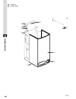
Page 29: ...B CALYDRA COMFORT 91 CALYDRA COMFORT DOMESTIC BOILERS CALYDRA COMFORT 80 CALYDRA COMFORT 100 R f 82025 96b 07 03 G B...

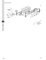
Page 30: ...92 B CALYDRA COMFORT 106 113 114 115 118 119 117 116 102 115 111 103 110 104 120 82070 85 100 BURNER 115 109 107 105 106 6001...

Page 31: ...RNER HEAD 1010753 109 GRILLE 277787 1010223 110 IGNITION ELECTRODE 277788 1002801 111 IONIZATION ELECTRODE 277789 1002802 113 HEAT EXCHANGER 277790 1010017 HEAT EXCHANGER E00606 1011136 114 COMBUSTION...

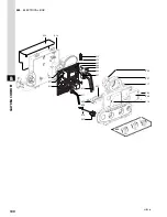
Page 32: ...94 B CALYDRA COMFORT 305 313 316 304 314 304 309 306 311 315 82070 86 200 FAN 300 SEALED CASE 227 202 213 205 221 228 201 230 212 303 304 214 216 206 204...

Page 33: ...H 24KW 1306697 AIR PRESSURE SWITCH 28KW 1307335 221 HOOD 1304712 227 TAPPING SCREW CBLSX D 4 2 12 5 1010847 228 TAPPING SCREW CBLSX D 6 3 13 277865 1010648 230 GASKET Flue bend turret 1300258 300 SEAL...

Page 34: ...96 B CALYDRA COMFORT 82070 87 400 GAS SECTION 431 409 442 403 435 437 436 406 433 434 405 401 515 449 432 445 438 402 412...

Page 35: ...E23492 1014420 04 VALVE D 2 90 E23493 1014420 05 410 FOAM SEAL 12x7 L 5M 265412 81273 04 412 GAS SECTION GASKETS KIT E23495 81837 431 RESTRICTOR E23497 1013017 432 GASKET Solenoid valve E23498 1013018...

Page 36: ...26 501 504 586 591 537 585 510 504 502 561 504 531 504 502 595 592 593 543 516 518 515 582 521 526 586 507 511 569 584 506 548 547 504 502 590 520 597 596 516 570 553 552 551 589 583 587 542 594 522 5...

Page 37: ...LTER 263545 37309 548 SHEET GASKET D 24 18 2 1 5 265091 22835 01 550 HEATING RETURN TUBE E23520 1014218 551 GAS TUBE 277853 1010040 552 PLUG E23521 1015245 553 O RING D 8 9 1 9 264374 24164 13 558 PUM...

Page 38: ...639 614 606 613 612 610 611 642 615 627 613 605 644 627 621 622 630 100 B CALYDRA COMFORT 82070 89 600 ELECTRICAL BOX 607 617 609 618 602 636 619 620 637...

Page 39: ...BOX 1302237 615 PRINTED CIRCUIT BOARD 1307627 617 ELECTRICAL BOX COVER 1303266 618 PLUG E00269 1011316 619 CLIP 277848 1002406 620 O RING D 5 7 1 9 E00621 1009834 10 621 TRANSMITTER OF LEDS 1302245 6...

Page 40: ...102 B CALYDRA COMFORT 82070 90 700 CHASSIS 800 FRONT CASE 706 704 703 706 701 813 802 801 714 713 712 709 803...

Page 41: ...366979 56676 06 704 CHASSIS 277866 1010028 706 TAPPING SCREW CBLSX D 6 3 19 1014516 709 FLEXIBLE PIPE KIT E23589 81824 712 SHEET GASKET D 12 8 1 2 1308868 713 CLIP 277841 1010005 714 O RING D 8 9 2 7...

Page 42: ...104 B CALYDRA COMFORT 82070 91 900 JIG PLATE PIPE FITTING 907 908 909 901 902 904 906 947 903 905 927 931 938 939 940 941 937 910 943 939 921 922 925 919 918 917 920 918 939 920 917 918 936 923...

Page 43: ...02775 07 FLOW REGULATORE 8L MIN WHITE E23605 1002775 08 FLOW REGULATOR 10L MIN BLUE E00631 1002775 10 FLOW REGULATORE 12L MIN RED E23606 1002775 12 FLOW REGULATOR 14L MIN PINK 277911 1002775 14 FLOW R...

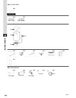
Page 44: ...1012 1019 1017 1013 1011 1018 1020 1014 1011 1001 1002 1015 1016 1017 1024 1004 1011 1020 1023 1018 1020 1018 1020 1011 1020 1018 1013 1019 D80 80 V HORIZONTAL FLUE KIT VERTICAL FLUE KIT DOUBLE FLOW F...

Page 45: ...704 1011 GASKET Flue bend turret 1300258 1012 FLUE BEND TURRET ASSY 1306699 1013 SLEEVE D 100 61310308 1014 FLUE DUCT SECOND SECTION 1306700 1015 AIR DUCT 1300298 1016 SEALING RING TRIM 366995 62079 1...

Page 46: ...0 ACCESSORIES 5030 5033 5035 5040 Acoustic Kit 5046 6001 6003 Simulating Descaling 6000 MAINTENANCE 6006 Spanner 6007 6002 Descaling 5020 5022 5021 5023 5015 5014 Connection FIRST FITTING Connection R...

Page 47: ...0 SLEEVE 1018789 5021 EXTREMITY CHOCK DRAUG DIV SIDE 1014400 5022 CHOCK DRAUGHT DIVERTER SIDE E00655 1010080 5023 SIDE CHOCK E00656 1010081 5030 ASSEMBLING JIG 1309247 5031 MECANICAL TIMECLOCK KIT 130...

Page 48: ...110...

Reviews: