9
Fig. 8
1
2
3
0
4
bar
Fig. 9
7
Installing the boiler
Fig. 10
L
A
A
A
A
Fitting the Horizontal Flue
The instructions for the vertical and biflux (twin pipe) flue options are included with the relevant adapter kits.
The standard flue supplied with the appliance is suitable for lengths from 300 mm minimum to 720 mm maximum. This means
for rear flueing, the standard kit will accommodate a maximum wall thickness of 600 mm, and for side flueing a maximum wall
thickness of 587 mm. This takes into account the minimum appliance side clearances of 5 mm.
If the fixing is a rear exit flue, the template provides the position of the centre for drilling the flue hole with a core drill.
If the flue is a side exit installation then calculate the position of the hole with a slope of 5 mm / metre away from the boiler to
the terminal. The flue should fall slightly to the terminal.
Place the boiler on the wall on the hanging bracket. Using (fig. 16) for reference, connect the gas and water pipes and the
valves to the base of the appliance using the tails provided. There is a 190 mm space between the valves and the wall to
make these connections.
Connecting the boiler to the system
Attention ! Connecting tails are delivered with the boiler. You could ask your local dealer or Chaffoteaux et Maury Ltd for first
installation tails kit or to replace existing boilers such as old Chaffoteaux et Maury models.
Before fitting the tails onto the connecting bracket, please check the correct location of the flow restrictor
L
(fig.10) on the main inlet.
Safety valve drains
The pressure relief valve tube is clear silicone. It should terminate below the boiler over a tundish or
22 mm pipe (see
I
fig 4) which should in turn discharge safely outside the premises. Care should be taken that it does not
terminate over an entrance or window or where a discharge of heated water could endanger occupants or passers by.
The system should be carefully checked for leaks, as frequent refilling could cause premature system corrosion or
unnecessary scaling of the heat exchanger. The pipe should be connected to a drain is the conditions described in the
relevant Brittish regulations.
Please check that you are familiar with the installation requirements before commencing work.(section 6)
Method of positioning the boiler on the wall.
The paper template can be used to ensure the correct positioning of kitchen cabinets etc. It also details the commissioning
instructions.
The paper template has to be fixed to the wall and used to locate the position of the hanging bracket and the centre for the flue
hole..
Drill and plug the wall and secure the hanging bracket using the screws provided. Remove the boiler from its packaging as
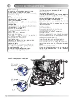
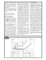
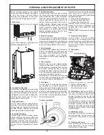
shown in fig. 9 and remove the outer case as shown in fig.10.
Summary of Contents for Calydra Comfort 100 Nat
Page 48: ...110...

