A
B
C
D
A
B
C
D
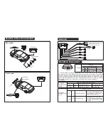
GENERAL INSTALLATION DIAGRAM
Control box
Reversing light
Sen
sor
Display
A
B
C
D
Sensor
MAIN UNIT
Speed signal (for back system, no use)
Control box
Display
Control box
Display
Back system
Front system
Speed
signal
Foot brake
Foot brake (for back system, no use)
Ground (same as front system)
Power (same as front system)
Turn on/off switch
Sensitivity adjustable
function
Dip switch1
front or back system choosing
UP
off
back system
0.3-1.5m
Down
on
0.3-1.0m
front system
DIP SWITCH OF MAIN UNIT
Control box
Dip Switch
1 2 3
*
*
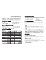
It has to realise the below functions:
A
.
there is switch on the power wire, used to control
the system turn on or turn off;
B
.
If the signal speed is set, when the real speed is lower than the
set speed, the system work normally(the switch on the power wire is in "Turn on" status, if you
turn it off, the system wouldn't work), if the real speed is higher than the set speed, the system
will not work automatically;
C
. If you didn't set the signal speed, when you press the foot brake,
the system will only work for 15s. But if there is obstacle, the system will start work
automatically.
Function:
Initial alarming mode control
UP
off
start to alarm at 1.5m
Yellow LED light
Down
on
Red LED light
start to alarm at 0.5m
Dip switch 2
(for back system,
no use)
Function:
anti-hook
UP
off
cancel the function
Down
on
start the function
Dip switch 3
(for back system,
no use)
The system will regard the hook
as an obstacle, The display will
show the real distance
the system will not regard the
hook as an obstacle, the display
will show 20cm less than the real
distance
*


