
User Manual B410PT
6
7
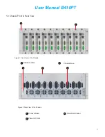
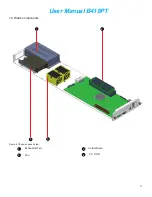
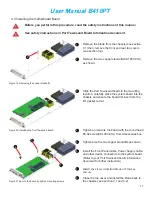
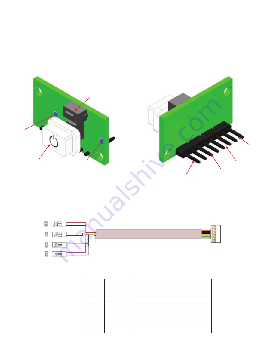
Chapter 2. System Board and Cable Features
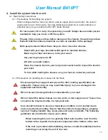
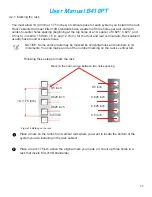
2.1 Front Panel Board (order #16-0123-01A)
The Front Panel Board supports several push buttons and status LEDs to centralize system
control, monitoring, and accessibility to within a common compact design. The following diagram
overviews the board layout and pin assignments for connectivity.
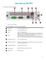
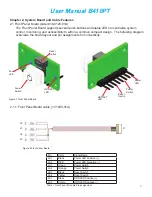
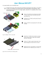
2.1.1 Front Panel Board cable (17-1035-01A)
Power
Switch
HDD ACT
LED
Power
LED
Power
Switch
Power
LED
HDD ACT
LED
Pin
Color
Signal Name
J2-1
Black
Power LED Positive (+)
J2-2
RED
Power LED Negative (-)
J3-1
Green
Power Switch
J3-2
Orange
Power Switch
J4-1
Black
Reset Switch
J4-2
Yellow
Reset Switch
J5-1
Black
HDD LED Positive (+)
J5-2
Purple
HDD LED Negative (-)
Table 1 Front Panel I/O cable Pin assignment
J2
J3
J4
J1
Figure 7 Front Panel Board
Figure 8 Front Panel Board
Reset
Switch
Reset
Switch
J5


